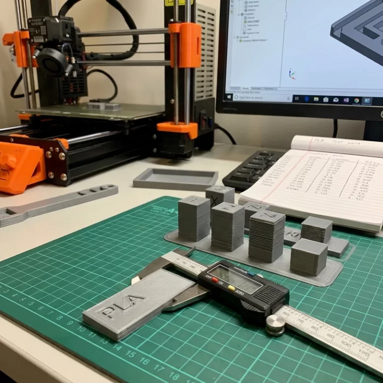
3D printed moving joints look easy in CAD and get annoying on the bench. A hinge that spins in the model can weld shut after printing. A gear pair that meshes on screen can rattle, grind or split at the tooth root. I do not judge these parts from the render anymore; I judge them from clearance coupons, cleanup time and how the joint feels after a few hand cycles.
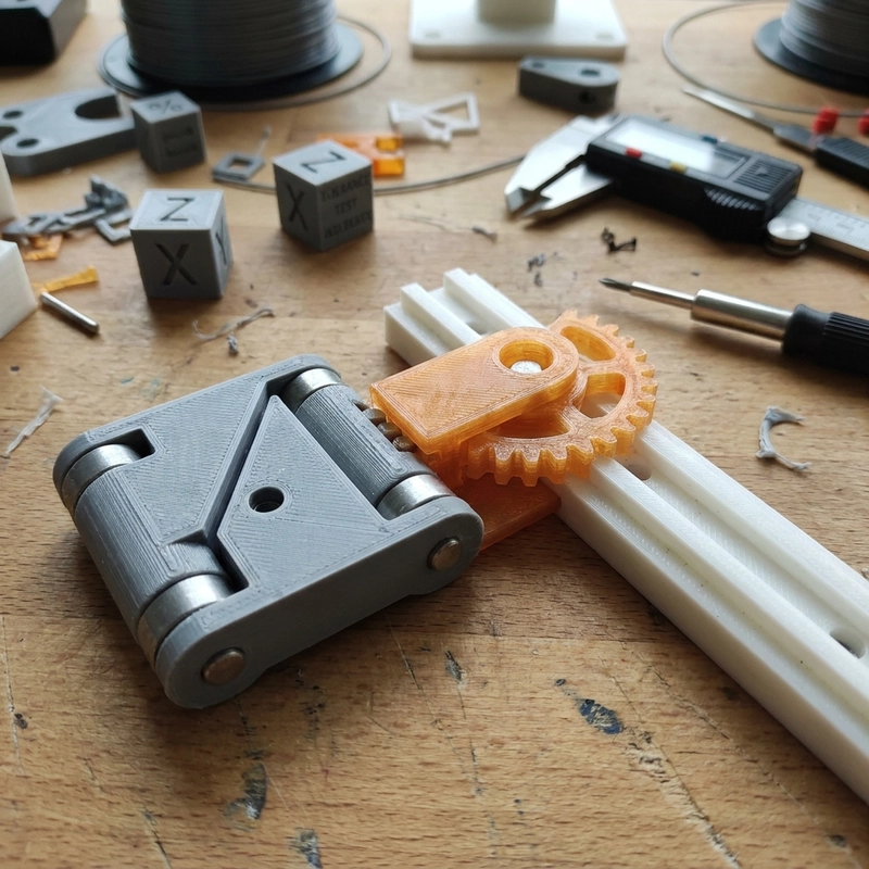
The basic trouble is simple: moving surfaces need a gap, but not a sloppy gap. For small hinges, gears, sliding rails, snap pivots and print-in-place mechanisms, the source gives 0.1-0.3 mm clearance as a practical starting range. It is not a magic number. The real value shifts with printer accuracy, layer height, material shrinkage, support marks, surface roughness and whether post-processing is allowed.
3D Printed Moving Joints Start With the Joint Type
A hinge is not a gear, and a sliding rail is not a snap pivot. A hinge pin mainly sees rotation and bearing pressure. A gear tooth sees repeated contact stress and root bending. A rail sees friction over travel length. A ball joint sees multi-axis contact and local wear. Treating them all as “a moving part” is where many prototypes go wrong.
For print-in-place hinges, I check whether powder, support or resin residue can escape the gap. For assembled hinges, I check pin tolerance and retention. For gears, I look at tooth root radius, backlash and layer direction under torque. For sliding rails, straightness and surface finish may matter more than raw tensile strength. If the design cannot define the failure mode, material choice becomes guesswork.
For powder-bed nylon mechanisms, the SLS nylon 3D printing guide is often relevant because there are no FDM support scars inside a moving gap. For fit-sensitive plastic parts, compare the clearance plan with engineering plastic 3D printing dimensional accuracy.
Clearance, Shrinkage and Material Behavior
A CAD gap is not the final physical gap. PLA usually shrinks less in ordinary FDM work, often around 0.1-0.3% depending on grade and settings. ABS can move more, around 0.5-0.8%, and it also likes to warp if enclosure control is weak. Nylon is tougher and better for wear, but it absorbs moisture and may change after conditioning. The same 0.2 mm gap can feel free in one material and locked in another.
Surface roughness eats clearance too. FDM leaves ridges. SLA resin can look smooth but still feel sticky if washing or curing is wrong. SLS nylon has a powdery surface that may need blasting, tumbling or exercise before movement feels clean. If a joint must move without sanding, design more clearance. If a joint must feel tight, print a coupon first.
Do not forget tolerance stack-up. A hinge with two leaves, one pin and two side faces can consume clearance in several places at once. A gear train may have backlash at every mesh and center-distance error at every shaft. A single 0.2 mm gap may be sensible, while five small errors in the same direction make the assembly feel sloppy or locked. Moving mechanisms need a stack-up sketch before they need a prettier render.
Material Choice for 3D Printed Moving Joints
PLA is fine for a classroom mechanism, display model or light-duty proof of shape. I would not put much faith in it for a snap hinge or a gear that sees repeated torque. The part may feel stiff, then crack without much warning. ABS gives better toughness and heat resistance than PLA, but warping joins the conversation. Nylon is usually more comfortable for functional rotation or sliding, especially in SLS or MJF.
Carbon fiber or glass fiber filled plastics are not an automatic upgrade. They can make a carrier stiffer, but small snap features may become less forgiving. For a gear housing, stiffness may help. For a flexing latch, toughness matters more. If PLA is being considered, read PLA 3D printing strength before trusting a brittle part in a moving assembly.
Coupons Before Full Assemblies
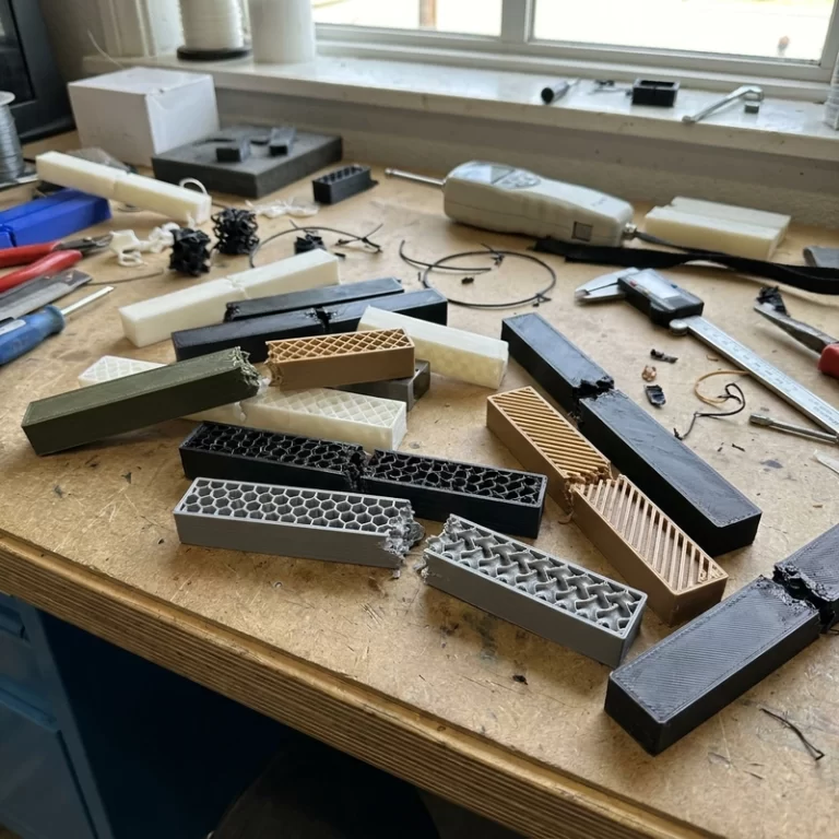
A small clearance coupon saves more time than it looks like. I like a strip with pins or slots at 0.1 mm, 0.2 mm, 0.3 mm and 0.4 mm clearance, printed in the same material, orientation and layer height as the real part. Test it raw, then after cleanup. That tells you how much clearance the process consumes before you print a six-hour enclosure with a fused hinge.
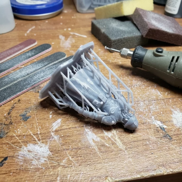
Do not force a stuck hinge through its full range on the first try. Free the joint gradually, remove support crumbs, blow out dust, and use a fine brush or compatible cleaner. Light sanding helps exposed pins and rails. Silicone oil can reduce startup friction on many plastic joints, but it cannot fix bad geometry. If the joint becomes loose after sanding, revise the design instead of calling the shim a production plan.
For repeated use, I also mark which surfaces actually wear. A hinge pin may polish in one band. A slider may scratch only at a rib. A gear may show white stress at the tooth root. That wear pattern is more useful than a general complaint that the mechanism feels rough. It points to clearance, material, orientation or local geometry instead of sending the whole design back to guesswork.
For 3D printed moving joints, the most useful drawing note is often not the material name. It is the movement range, target feel, allowed cleanup, expected cycles and the surfaces that cannot be sanded. Those notes stop the part from becoming a blind tolerance experiment.
The ISO/ASTM 52900 additive manufacturing vocabulary is useful for formal terminology. For the actual RFQ, be more practical: send movement range, load direction, cycle expectation, material preference, target clearance, visible surfaces and whether post-processing is allowed. 3D printed moving joints are practical when clearance is tested, the material matches the wear problem, and cleanup is part of the design. Skip one of those, and the joint may still print. It just may not move.