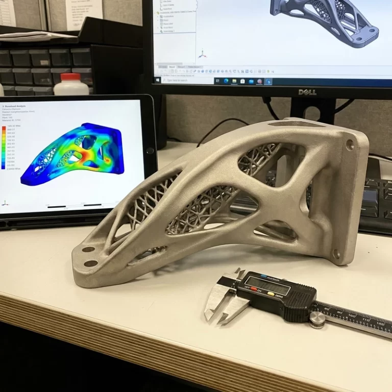
3D printing support design is where many nice-looking CAD files pick up scars, broken edges, wasted material, and avoidable finishing cost. Support is not just a slicer checkbox. It decides where the part is held, where it is damaged, and how much work is needed after printing.
I review support before printing, not after removal. Once a support point is sitting on a visible face, a sealing surface, or a fine figurine detail, the finishing team is already paying for that decision.
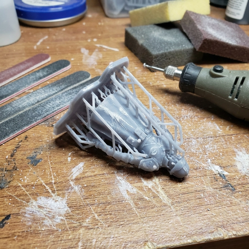
3D printing support design starts with orientation
The common 40-45 degree overhang rule is only a starting point. A short 40 degree edge may print cleanly, while a long thin 55 degree lip can curl, vibrate, or leave a rough underside. Before adding more support, I rotate the part and ask which surfaces are allowed to carry marks.
For appearance parts, I protect the visible face first. For fixtures, I protect the functional face and load path. For resin parts, peel forces and suction matter. For metal printing, support also helps conduct heat and restrain distortion. For SLS and MJF nylon, the powder bed supports most geometry, so the issue shifts toward thin feature distortion, powder removal, and cooling balance.
Contact points make or break 3D printing support design
Contact size is a tradeoff. Small points reduce scars but may fail during printing. Larger points hold better but leave raised marks, pits, or torn material after cutting. In SLA, support contacts around 0.5-1 mm are common depending on resin and part size. In FDM, support gaps around 0.2-0.5 mm are often starting ranges, but the material and layer height decide whether the support separates or welds to the part.
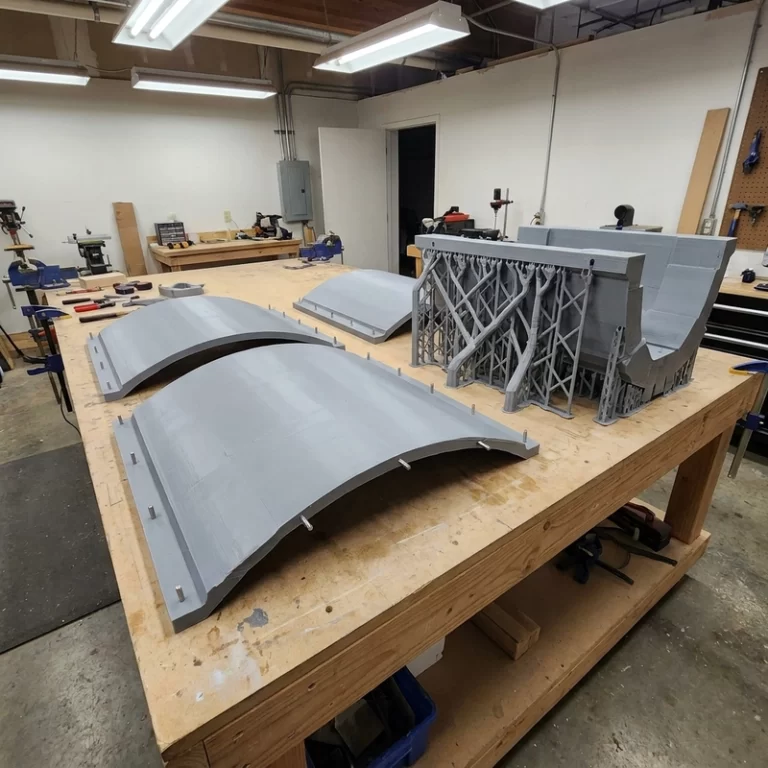
Tree supports can reduce material and touch fewer places, but they are not magic. A broad flat roof may still need stable support. A tiny cosmetic detail may need a support point that is easy to sand. I move contacts onto hidden backs, extra stock, thick edges, or areas that will be painted or machined. A support mark on a hidden face is cheap. The same mark on a display surface is a rework problem.
| Process | Main support problem | What I check |
|---|---|---|
| FDM | Drooping, welding, rough underside | Overhang angle, Z gap, density, cooling |
| SLA | Peel force and contact scars | Point size, hidden placement, staged removal |
| SLS/MJF | Thin feature warp and trapped powder | Wall thickness, escape holes, nesting |
| Metal SLM | Heat stress and difficult removal | Anchoring, machining allowance, access |
Removal workflow is part of the design
Pulling supports off in one motion is fast until it tears a corner. I prefer staged removal: cut the support tree away, leave a small stub, then trim and sand the contact area. Resin supports are often easier to remove before final full cure, but the part can deform if it is handled roughly while still green.
Soluble supports such as PVA help with some FDM cavities and delicate surfaces, but they add drying needs, wash time, and material compatibility questions. If the support material prints poorly or absorbs moisture, the model material can be fine and the part still fails.
3D printing support design notes before release
I mark visible surfaces, mating faces, overhangs, removal direction, finishing allowance, and any area that cannot tolerate support scars. For surface impact, the related article on 3D printing surface roughness is useful. For resin appearance work, SLA resin 3D printing explains why supports, washing, and curing have to be planned together.
NIST additive manufacturing resources are useful for neutral process background. On the shop side, the practical rule is this: support should hold the part during the build, remove predictably, and touch the least important surfaces. 3D printing support design is successful when cleanup is boring.
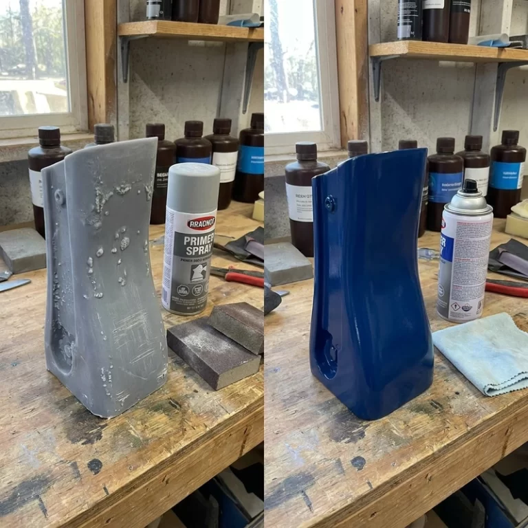
For the first sample, I inspect support scars before any heavy sanding. That is when the real support decision is easiest to see. A crater on a hidden underside may be acceptable. The same crater on a sealing surface, a painted visible wall, or a character face is not. If the surface will be coated, I still check the raw scar because primer cannot hide deep torn material without changing the shape.
I also look for support that solves one problem and creates another. Dense supports under a flat roof may prevent sagging but trap resin, powder, or tool access. Sparse supports may save material but let an edge curl. Good 3D printing support design is usually a compromise that is documented: where supports were placed, why those surfaces were chosen, and what cleanup allowance was expected.
For repeated parts, I keep photos of the supported orientation and the cleaned surface. It is not fancy documentation, but it prevents drift. If the next batch moves the support to a different face, changes point size, or uses a different removal sequence, the surface result can change even when the CAD file is identical.
That tiny record saves awkward repeat-sample surprises.