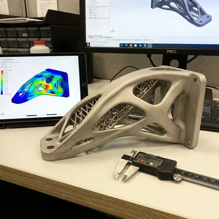
3D printed part strength depends on the load path, material, geometry and manufacturing conditions, not on infill density alone. A thin boss, sharp internal corner, unfavorable layer direction or overloaded screw connection can remain a weak point even when more material is added inside the part.
Before changing print settings, identify the likely failure mode. Bending, separation between layers, stripped threads, cracked insert seats, heat-related deformation and sliding wear require different checks.
3D printed part strength begins with the weak plane
Build direction can affect mechanical behavior, particularly in FDM parts where a load may cross layer interfaces. Review the direction of the applied force, support placement and finish-sensitive faces together. Changing orientation can improve one feature while creating a different manufacturing or assembly concern.
For a loaded bracket, handle, clip or hinge, mark the main force and fixation points before selecting an orientation. If no single build direction meets the requirements, review a split-and-assemble design as an alternative. Fasteners, inserts or bonded joints introduce their own connection checks; splitting is not automatically stronger.
Infill is useful, but walls usually earn their keep first
There is no universal infill percentage for display models, fixtures or heavy-duty parts. Specify the shell, load-bearing sections, infill pattern and density around the actual geometry and use. Prusa’s infill guidance explains the role of perimeters and compression resistance. It is process background, not a load rating for a finished part.
For many parts, extra perimeters, thicker bosses, ribs, fillets, and better screw-hole design do more than a big infill jump. Infill supports the shell and resists crushing, but it does not repair a bad corner radius or a screw placed too close to an edge.
| Failure sign | Likely cause | Better first check |
|---|---|---|
| Layer split | Load across weak layer bond | Orientation, temperature, cooling, material dryness |
| Boss cracks | Thin wall or sharp root | Boss diameter, fillet, insert design |
| Clip snaps | Brittle material or short flex zone | Material toughness and bend radius |
| Thread strips | Plastic thread overloaded | Metal insert or post-machining |
| Part bends too much | Low stiffness or thin section | Rib layout, material modulus, wall thickness |
Material choice changes the failure mode
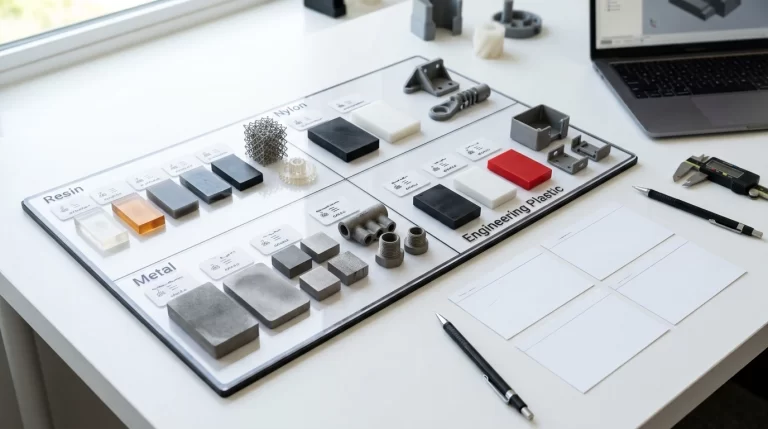
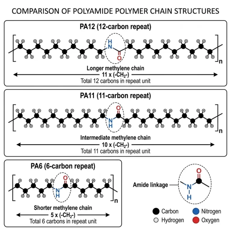
PLA is stiff and easy to print, but it can be brittle and heat-sensitive. ABS is tougher and more heat resistant, yet it needs better thermal control to avoid warping. Nylon, especially SLS or MJF nylon, is often useful for hinges, clips, gears, and wear surfaces because it has good toughness. Filled nylon can improve stiffness, but carbon or glass fiber can make impact behavior less forgiving and may wear FDM nozzles.
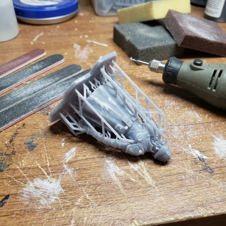
Resin grades need separate review. An appearance resin and a resin selected for compliant features may behave differently; an ABS-like description is not complete equivalence to molded ABS. For screws, bending or repeated handling, agree a relevant feature sample and checking method before extending the result to a batch. Formlabs’ post-curing guidance explains why processing conditions affect resin properties; it does not establish Zesmir test results.
3D printed part strength checks before a functional order
Review load direction, wall sections, build orientation, material, temperature exposure, fastener tightening, inserts and wear surfaces. Mark any feature that may require machining or a separate inspection. Include those requirements with the quotation file package, rather than expecting the supplier to infer the intended use from geometry alone.
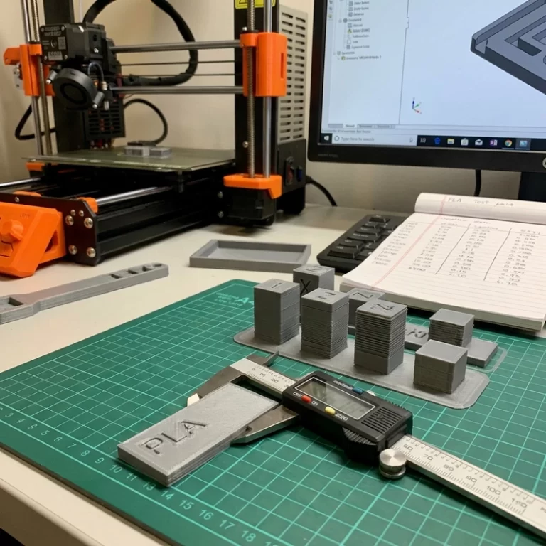
For a load-bearing trial, record the proposed material grade, build and processing conditions, fixture, applied load and acceptance criteria. Material datasheets support selection, but a datasheet specimen is not the finished component. A sample check does not establish safety certification or all service conditions.
Review the load path before paying for more infill. Orientation, wall design, material behavior and connection geometry should be considered together, with sample checks focused on the intended use.
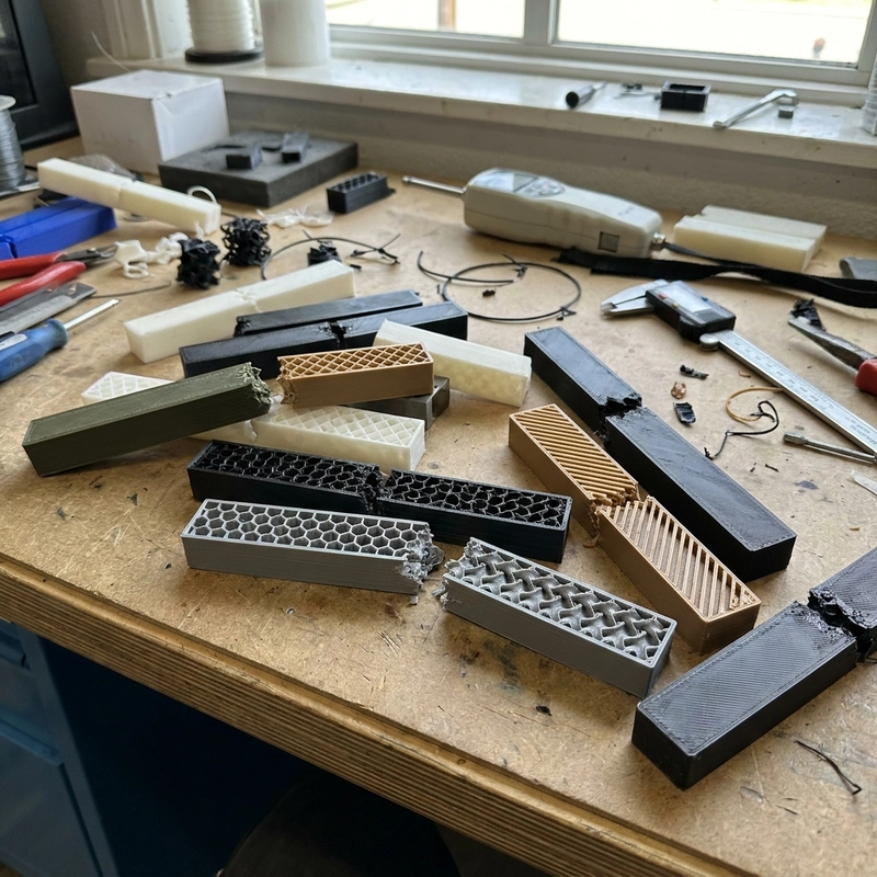
A representative feature sample can help investigate a connection or thin section before a full build. Define a controlled checking procedure and appropriate safety precautions; do not casually overload an installed part or equipment. A fracture location can guide further investigation, but it does not identify the cause conclusively without checking material, processing and test conditions.
For repeat parts, agree which material, manufacturing and finishing information should accompany the approved sample. Moisture, processing and curing conditions may affect results. Reference samples and inspection notes can support comparison with later parts; they are not proof that Zesmir already performs an unrecorded test on every order.
For a grip or carry-handle sample, see SLA vs FDM for a handle prototype. It separates surface review from mounting and loaded trials so the sample specification matches the question being tested.