Topology optimization for 3D printing can remove a surprising amount of material, but the load case matters more than the mesh. I get suspicious when the first thing shown is an organic-looking bracket with no explanation of fixed faces, bolt preload, side load, vibration, heat, inspection or support removal. A beautiful optimized shape is not a qualified part.
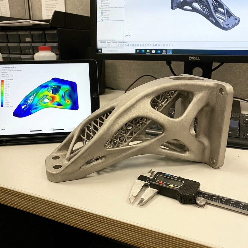
The workflow is useful when it is treated as engineering. Start with a design space. Define keep-out zones, fastener interfaces, load points, supports and performance targets. Let finite element analysis suggest where material is doing useful work. Then rebuild that rough result into manufacturable CAD and check it again. The raw optimization output is usually a suggestion, not a production file.
Topology Optimization for 3D Printing Starts With Inputs
A bracket rarely sees only one neat vertical force. It may see side impact, vibration, assembly preload, thermal expansion or handling abuse. A drone arm may be stiffness-limited, not strength-limited. A robotic link may care about torsion. If the analysis only includes the cleanest load, the algorithm may remove material needed in the real part.
I would rather see several imperfect but honest load cases than one polished simulation. Include bolt preload when fasteners matter. Include off-axis load when the part may be handled roughly. Include machining clamp loads if post-machining is planned. Lightweight design should remove unused material, not unknown material.
Constraints can be as important as loads. Keep-out zones around tools, sockets, cables, labels and inspection probes should be included before the solver starts removing material. So should flat pads for fasteners and surfaces for CMM measurement. I have seen optimized parts become awkward because nobody left room for a wrench, a clamp or a fixture. That is not a software problem; it is an input problem.
This topic connects directly to metal 3D printing aerospace parts when weight is the business reason. For metal manufacturability, metal 3D printing support design should be reviewed before a topology result is sent to the machine.
Manufacturing Rules Change the Optimized Shape
SLM metal printing needs support, heat flow, powder escape and residual-stress control. A rib that looks efficient may distort during the build. A hidden cavity may trap powder. A down-facing surface may be too rough for fatigue. SLS nylon gives more geometric freedom, but it still has wall thickness, powder removal and tolerance limits. FDM is useful for early shape checks, but layer anisotropy can make the part weaker than an isotropic simulation assumes.
Lattices are not automatically better. They can reduce weight, tune stiffness or create energy absorption. They can also trap powder, complicate CT inspection, create cleaning problems and make surface finishing nearly impossible. For many industrial parts, clean ribs and hollow sections beat a dense lattice that nobody can inspect.
Process choice should come before the final shape is frozen. SLM can make thin metal ribs, but support removal, heat distortion and machining access decide whether those ribs survive manufacturing. SLS nylon can make enclosed geometry, but powder escape holes and minimum wall thickness still matter. FDM can prove a concept quickly, yet layer direction may exaggerate or hide a weakness. A topology result designed for one process should not be quietly transferred to another.
CAD Cleanup After Topology Optimization for 3D Printing
The raw mesh often needs smoothing, feature cleanup and real datums. Fastener bosses should remain inspectable. Bearing seats and sealing faces may need machining allowance. Thin tendrils should become manufacturable ribs with minimum thickness. Sharp turns should receive fillets. Do not remove every flat face; real parts need places for clamping, measurement, labels and post-processing.
After cleanup, rerun FEA on the CAD that will actually be printed. Check stress, displacement and safety factor. If fatigue, vibration or heat matters, simple static stress is not enough. For metal parts, surface condition, porosity, heat treatment and machining all affect performance. For polymer parts, creep, temperature and moisture matter.
The first physical print should not be treated as proof just because it survived handling. Check the same features the simulation depends on: rib thickness, hole position, boss flatness, support-contact cleanup and any surface that carries load. If the part will be machined after printing, inspect before and after machining. The machining step can reveal porosity, move a thin wall or remove material from a feature the solver assumed was still there.
File handoff is where a lot of optimized parts lose discipline. Send the cleaned CAD, not only the organic mesh. Mark critical datums, forbidden support zones, machining allowance and inspection surfaces. If a lattice is used, show powder escape paths and the minimum feature size expected from the chosen process. Topology optimization for 3D printing should leave the manufacturing team with fewer guesses, not more.
The NIST additive manufacturing resources are useful background for process and measurement language. They do not replace validation. A practical RFQ should include design space, load cases, constraints, target material, safety factor, quantity, critical surfaces, finish and inspection requirements. Topology optimization for 3D printing is strongest when it becomes a disciplined loop: define, optimize, clean up, print, inspect and test.