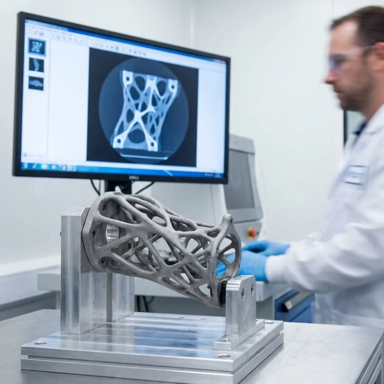
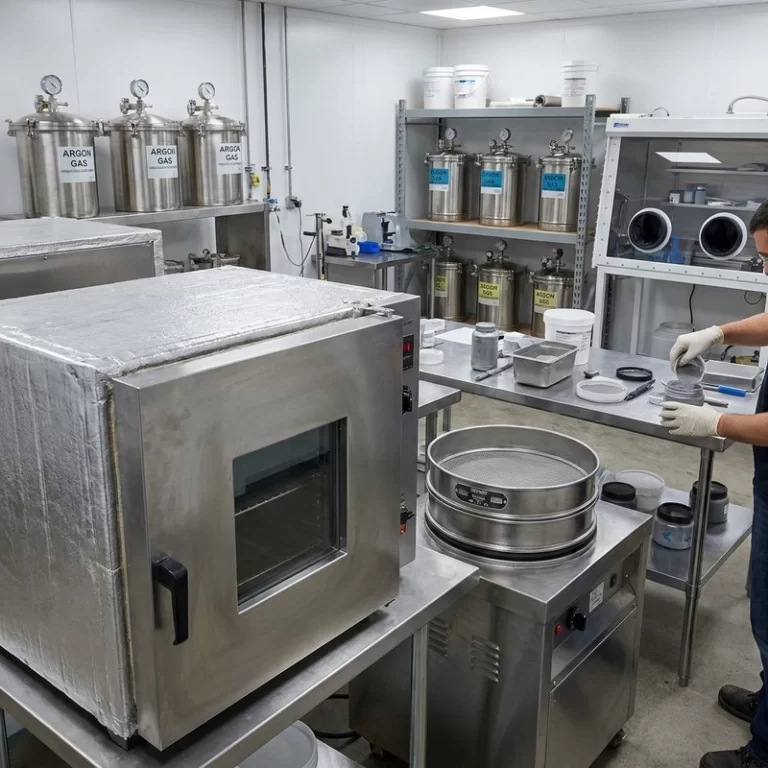
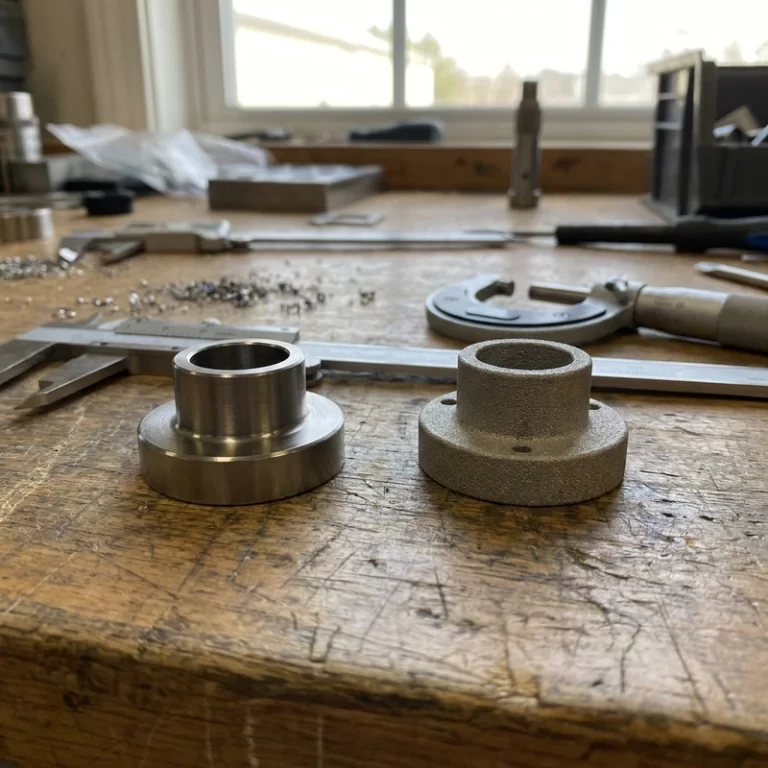
Metal 3D printing support design is not just temporary scaffolding. In SLM and related metal powder-bed processes, supports hold the part, conduct heat, resist residual stress, and protect the build from recoater collision or distortion. A support that looks wasteful in software may save the job. A support that looks efficient may scar a critical face or fail halfway through the build.
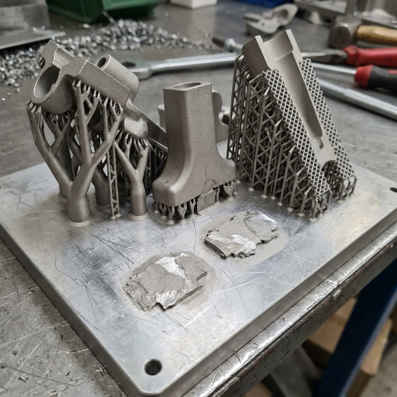
I do not aim for the least support possible. I aim for enough support in the right places, with a removal plan that does not destroy the part. Metal 3D printing support design should be reviewed together with build orientation, heat flow, surface finish, machining stock, and inspection requirements.
Metal 3D printing support design and waste
The source gives an example where a 100 g part used 80 g of support. That looks like material waste, but the real cost is broader: machine time, powder use, support cutting, grinding, tool wear, surface repair, and possible scrap if the support removal damages a sealing or mating surface. Saving 20 g of support is not a win if the build fails or the part needs hours of repair.
Support-free design can help. Chamfering a 90-degree ledge into a 45-60 degree self-supporting angle may remove support and improve heat flow. Hollowing a solid block can reduce stress and support mass if powder escape is designed. Splitting a part along non-critical seams can let each section print with fewer scars, then be welded, brazed, bolted, or machined as needed.
Build orientation is the first support decision. Rotate the part and support volume changes, but so do distortion, surface quality, and machining access. A low-support orientation that puts a rough down-facing surface on a sealing face is not low cost after repair. I look at the whole chain before approving orientation.
For general support logic outside metal, Zesmir’s 3D printing support design is useful. For the metal process context, read the SLM metal 3D printing overview.
Tree, lattice, and local metal supports
The source gives design references such as tree support stems around 2-3 mm, branch angles around 30-45 degrees, lattice support infill around 10-20% for some support columns, 0.3 mm breakaway necks in some examples, and angled supports around 15-30 degrees for certain geometries. These are not universal values. Alloy, layer thickness, machine, part mass, and thermal behavior decide the real support design.
Tree supports can reduce contact area on curved surfaces. Lattice supports can carry broader zones with less solid material. Dense local supports may be needed under heavy overhangs or thermal hot spots. Breakaway necks can reduce removal damage, but if they are too weak, the support may fail during printing. Metal support design is a tradeoff, not a decoration pattern.
Thermal anchoring is the part many beginners miss. A support conducts heat away from a hot overhang into the plate or surrounding structure. If the support is too thin, the area can overheat, roughen, curl, or crack. If the support is too heavy, it may be expensive to remove and leave deep scars. The right support is often local: strong where heat and stress demand it, lighter where only geometry needs help.
Metal 3D printing support design for surface damage
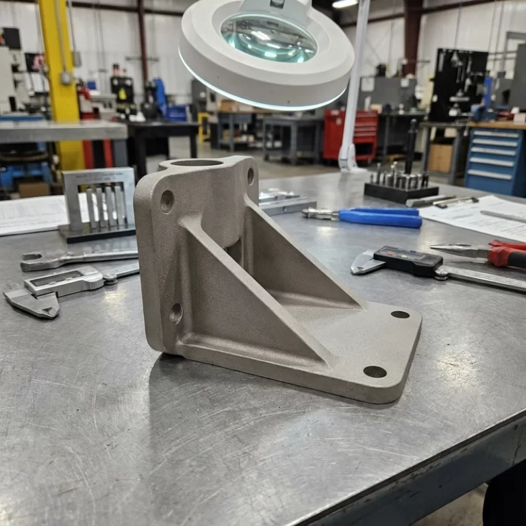
The source suggests support-part gaps around 0.15-0.2 mm for some stainless steel and titanium examples. In metal printing, that interface is also a heat path. Too little contact can fail to anchor or cool the part. Too much contact creates deep scars, difficult removal, and more machining. Visible, sealing, sliding, or fatigue-sensitive surfaces should avoid support contact when possible.
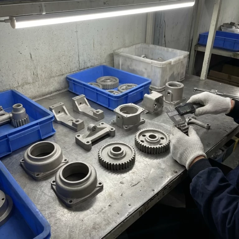
Removal access should be checked before printing. Can a grinder, saw, EDM wire, or machining tool reach the support? Will support scars be removed by post-machining? Are any supports trapped inside flow channels? If the tool cannot reach the support, the design is not finished.
Critical surfaces need labels in the file review. Mark datum faces, sealing faces, cosmetic faces, fatigue-sensitive zones, and areas planned for machining. Without those marks, support placement becomes a guessing game. The person generating supports may not know which face the assembly depends on.
Support marks can also change fatigue behavior. A rough scar on a decorative face may be ugly. A rough scar on a loaded transition may become a crack starter. If the part will see cyclic load, support placement and surface repair should be reviewed with that risk in mind.
For neutral process language, NIST additive manufacturing is a useful reference. Standards and terminology help, but the build still depends on practical support trials and inspection.
Support trials before expensive builds
For a new alloy, new machine, or difficult geometry, I would rather print a small support trial than gamble on a full plate. Test contact gap, branch diameter, lattice density, breakaway necks, and removal method. Evaluate the support after the same stress relief, blasting, or finishing route planned for the real part. A support that breaks cleanly before heat treatment may behave differently afterward.
An RFQ should mark cosmetic faces, machined faces, load paths, overhangs, internal channels, and inspection-critical surfaces. Metal 3D printing support design is successful when the part prints, cools, detaches, finishes, and passes inspection without unnecessary material or avoidable surface damage.
For difficult parts, include the planned removal method with the quote: band saw, EDM, milling, grinding, or hand tools. Support design that ignores removal is only half a plan. Metal 3D printing support design should end with a finished part, not a clever support tree stuck in a place nobody can reach.