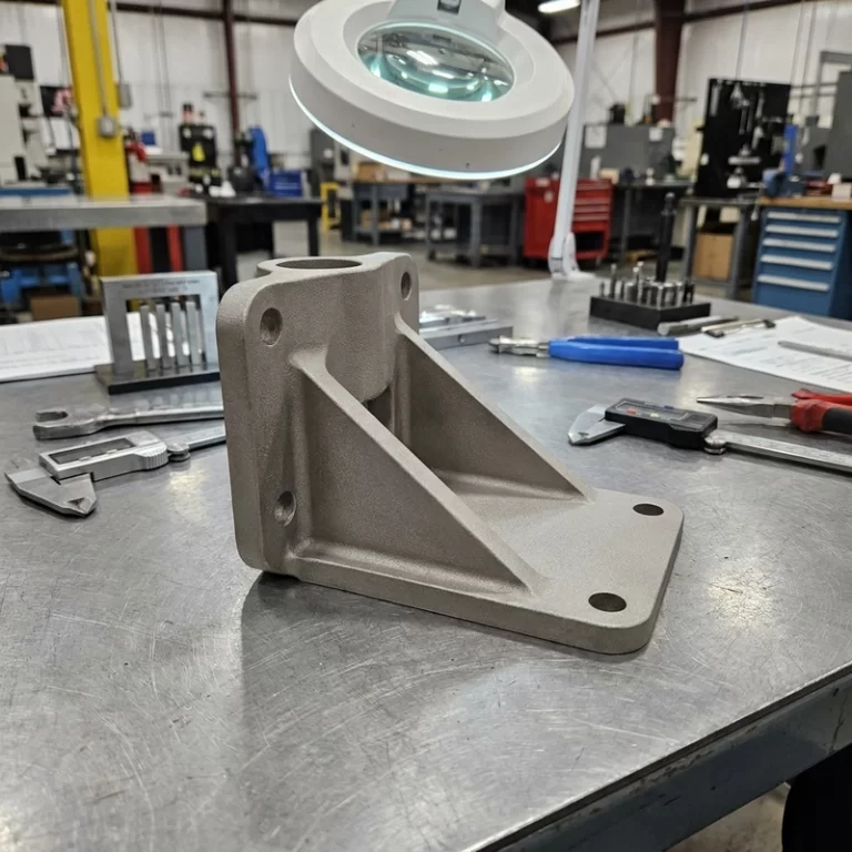
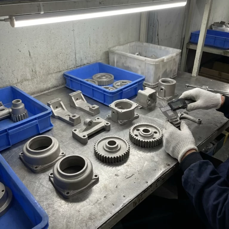
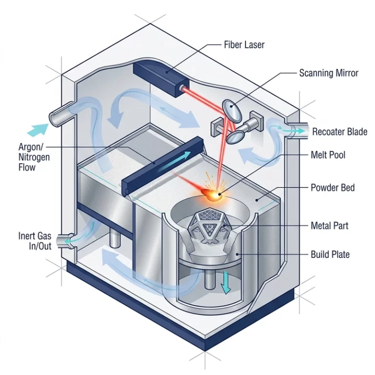
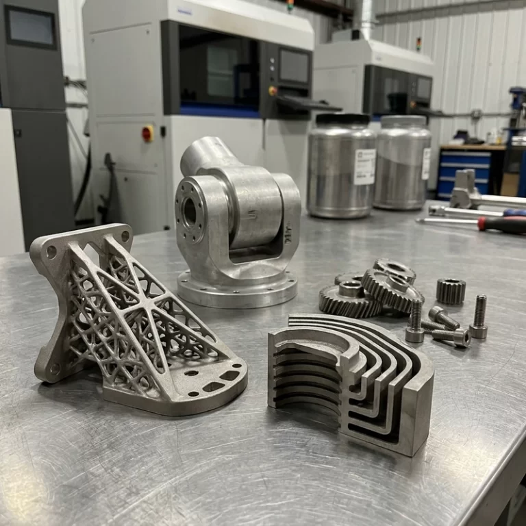
SLM metal 3D printing overview articles can make the process sound like a metal version of desktop printing. It is not. SLM, often discussed as laser powder bed fusion, melts thin layers of metal powder with a laser inside a controlled chamber. The printed part may still need stress relief, support removal, machining, blasting, polishing, heat treatment, coating, and inspection before it is usable.
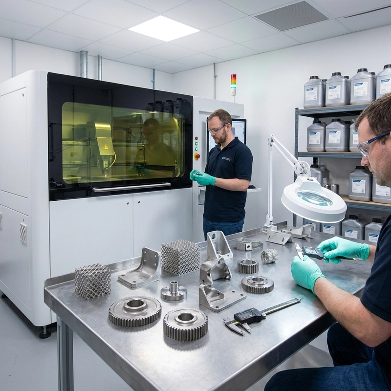
I use SLM when the geometry justifies the process: internal channels, lightweight brackets, integrated assemblies, complex cooling, or custom metal parts in low volume. I do not use it to replace a simple machined plate. A good SLM metal 3D printing overview should include the limits as clearly as the strengths.
SLM metal 3D printing overview of materials
Common SLM materials include 316L stainless steel, 17-4PH stainless steel, Ti6Al4V titanium alloy, AlSi10Mg aluminum alloy, and nickel superalloys. 316L is used for corrosion resistance and general industrial parts. 17-4PH can offer strength after heat treatment. Titanium is attractive for strength-to-weight ratio and some biomedical or aerospace-style development work, but oxygen pickup, residual stress, and fatigue control matter. Aluminum is useful for lightweight and thermal parts, yet distortion and post-machining are common discussions.
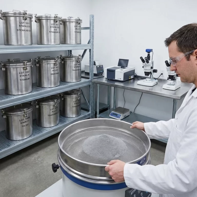
Material name does not equal final property. Powder quality, particle size distribution, oxygen level, reuse history, laser parameters, build orientation, heat treatment, and inspection all affect the part. For powder-control details, see Zesmir’s article on metal 3D printing powder quality and metal powder preprocessing.
Workflow in an SLM metal 3D printing overview
The workflow starts with design review. Thin walls, trapped powder, unsupported overhangs, sharp stress risers, and inaccessible supports should be found before printing. The part is oriented, supported, sliced, and nested. Powder is prepared and loaded. The chamber is purged with inert gas or otherwise controlled depending on machine and material. The laser melts each layer, and the build cools before the part is removed.
After printing, the part usually remains attached to the build plate with supports. Stress relief may happen before cutting. Supports are removed by cutting, grinding, EDM, or machining. Critical datums are often machined. Surfaces may be blasted, polished, passivated, anodized, or coated depending on alloy and use. None of that is an optional footnote for serious metal work.
Design for SLM is different from design for CNC. A machinist worries about tool access. An SLM engineer also worries about powder escape, heat flow, overhangs, residual stress, and support removal. A deep blind channel may print but trap powder. A large solid block may build stress and cost. A down-facing surface may be rougher than the same feature machined from billet.
Where this SLM metal 3D printing overview sees risk
Typical defects include lack of fusion, keyhole porosity, balling, cracking, recoater strikes, warping, support failure, and rough down-facing surfaces. Lack of fusion may involve low energy density, poor powder spreading, or contamination. Keyhole porosity can appear when excessive energy creates unstable vapor cavities. Warping and cracking often involve residual stress, geometry, support, and thermal history together.
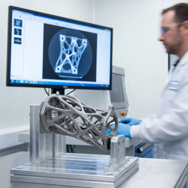
Inspection depends on risk. A decorative stainless part may need visual and dimensional checks. A pressure, fatigue, or safety-related part may need CT, X-ray, dye penetrant, tensile coupons, hardness testing, metallography, or process qualification. Do not let a shiny metal print stand in for validation.
Build orientation decides several costs at once. It changes support volume, surface finish, residual stress, recoater risk, machining access, and sometimes strength direction. I prefer reviewing orientation with the finishing plan visible. The cheapest orientation in slicing software may place scars on a sealing face or make post-machining awkward.
Powder removal is another design item, especially for internal channels. If the channel is too small, too long, or has no escape route, loose powder can remain inside. A conformal cooling insert or fluid part should include a cleaning and inspection plan before the build starts. Printing an internal feature is only useful if it can be cleared and verified.
Metal support design deserves its own review. The related Zesmir article on metal 3D printing support design covers waste, thermal anchoring, and surface damage in more detail.
For neutral process terminology, ISO/ASTM 52900 is a useful external reference. For broader metal additive manufacturing context, the NIST additive manufacturing resource is also useful.
When SLM is worth quoting
SLM makes sense when it reduces assembly, creates geometry that machining cannot reach, or produces low-volume metal parts without tooling. It is weak for simple shafts, plates, flat brackets, and high-volume commodity parts. Tight tolerances usually need CNC finishing. For process choice against binder jetting, read SLM vs binder jetting metal 3D printing.
An RFQ should include alloy, quantity, critical dimensions, load, heat, corrosion, fatigue, pressure condition, heat treatment, surface finish, post-machining, and inspection level. SLM metal 3D printing overview work is useful only if it leads to a real process plan, not just a metal-looking print.
If any of those items are unknown, start with a prototype and an inspection coupon. SLM is powerful, but it rewards defined assumptions. Guessing the alloy, finish, tolerance, and inspection plan after printing is where metal additive work gets expensive.
For buyers, the cleanest early decision is whether the raw printed surface is acceptable anywhere. If every functional face needs machining, the quote should include stock allowance and CNC access. SLM can create the shape, but it should not be forced to do the job of a finishing process.