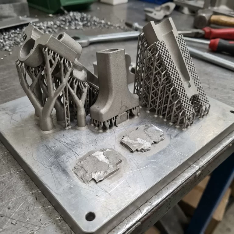
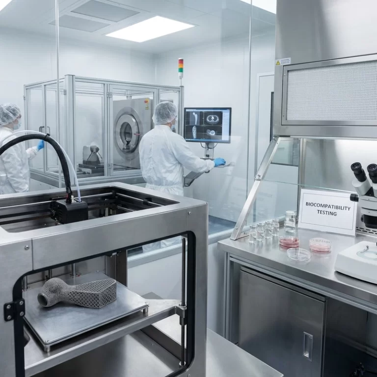
Metal 3D printing aerospace parts are attractive because every gram matters, but weight saved on a screen does not count until the printed part survives process control, inspection and qualification. I would not call an aerospace bracket successful just because topology optimization made it 40% lighter. The part still has to print, cool, detach, finish, measure and pass the right validation route.
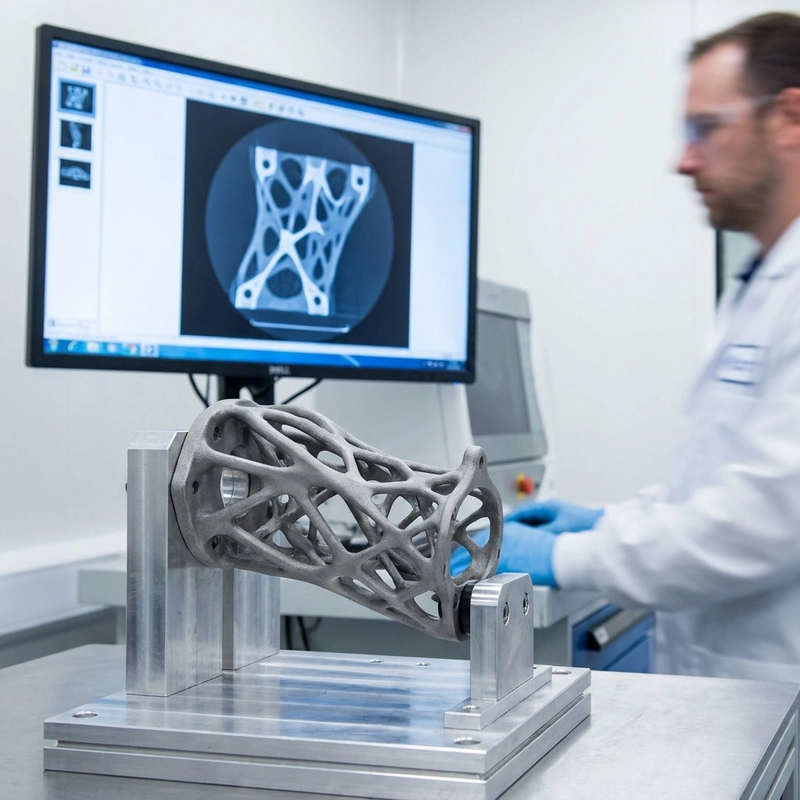
The source material mentioned topology-optimized titanium brackets with weight reductions around 35-47% in some aerospace cases, part consolidation such as fuel-nozzle style assemblies, and lattice porosity in the 30-70% range. Those are useful engineering examples, not promises. Metal 3D printing aerospace parts only make sense when the geometry gain is large enough to justify powder control, support work, heat treatment, machining and documentation.
Metal 3D Printing Aerospace Parts Need a Real Load Path
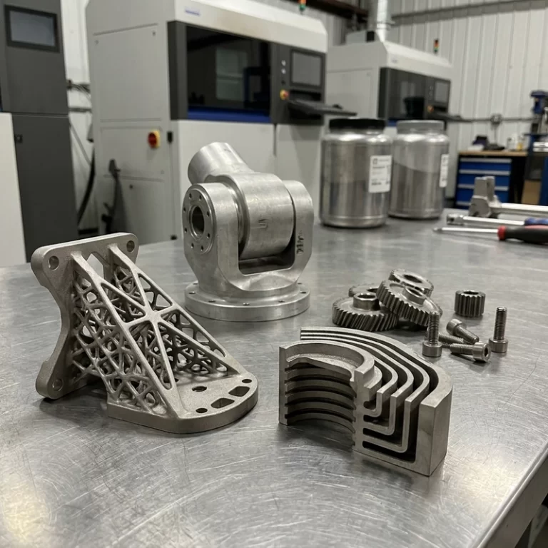
Aerospace designers often use additive manufacturing for three weight routes: topology optimization, part consolidation and lattice structures. Topology optimization removes low-stress material while keeping the load path. Consolidation replaces several welded or fastened parts with one printed body. Lattices reduce mass or tune stiffness inside volume that would otherwise be solid.
Each route brings a different failure risk. A thin optimized rib may be hard to support or inspect. A consolidated part may be harder to repair because one defect scraps the whole assembly. A lattice can trap powder, hide defects and create fatigue-sensitive nodes. I would rather see one clean load case and an inspection plan than a dramatic lattice screenshot with no powder escape route.
Orientation is one of the first practical arguments. Put the part in the build chamber only for minimum support and you may create a poor fatigue direction. Rotate it for strength and you may create support scars on a sealing face or a bolt pad. For aerospace-style metal work, I normally ask which surfaces will be machined, which surfaces must stay as-printed, and whether internal powder can really be removed after the build. If that discussion happens after printing, the design is already late.
This is where topology optimization for 3D printing becomes practical only after manufacturability cleanup. For the metal process chain itself, pair it with the SLM metal 3D printing overview.
Materials, Powder and Fatigue Control
Ti6Al4V is common because of strength-to-weight ratio and corrosion resistance. AlSi10Mg may be chosen for lightweight thermal structures. Nickel alloys such as Inconel 718 appear when temperature and oxidation resistance matter. Stainless steel may still be useful for tooling, fixtures or non-flight hardware. The alloy name is only the beginning.
Aerospace parts often fail by fatigue rather than one clean overload. Additive surfaces, support scars, lack-of-fusion defects, porosity and rough down-facing areas can all hurt fatigue life. Titanium is sensitive to oxygen pickup and surface condition. Aluminum needs heat-treatment and cracking risk reviewed. Nickel alloys need tight process windows. Powder batch chemistry, particle size, oxygen, reuse and storage records are not paperwork decoration; they belong to the part history. The article on metal 3D printing powder quality is the right next read here.
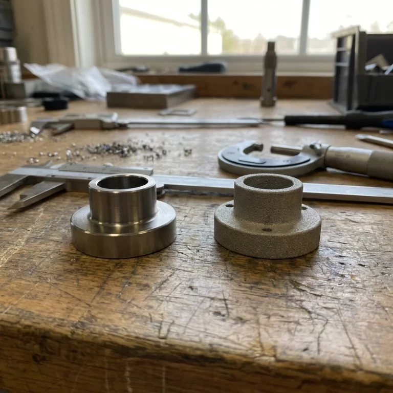
Surface finish should not be treated as cosmetics only. A rough downskin can become a crack starter. A support contact area can need grinding, EDM, CNC cleanup or local polishing, and that cleanup may change the final dimension. If a bolt hole, bearing seat or sealing land matters, leave machining stock and define a datum scheme before printing. A near-net-shape metal print without datums is a difficult part to rescue.
Inspection for Metal 3D Printing Aerospace Parts
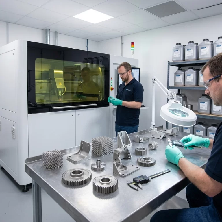
Inspection should be defined before printing. CT or X-ray may be needed for internal defects. Dye penetrant can reveal cracks. CMM measurement checks datums. Surface roughness checks matter where fatigue or sealing is involved. Coupons may need to be built with the part, using the same orientation and heat treatment. If HIP, stress relief or machining is part of the process, those steps must be in the plan from the first quote.
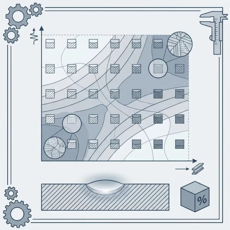
The coupon plan deserves real attention. A coupon printed somewhere convenient on the plate is not always evidence for a thin rib on the opposite side of a hot build. If mechanical properties matter, the coupon orientation, location, heat treatment and surface condition should match the part logic as closely as the specification requires. For a non-flight demonstrator, the plan can be lighter. For qualification work, casual coupons create false confidence.
The NIST additive manufacturing resources are useful as a neutral reference for process language and measurement discipline. They do not qualify a flight part by themselves. Qualification still belongs to the applicable aerospace program, customer specification and regulatory pathway.
When Aerospace Metal Printing Is Worth It
Metal printing is not automatically better than forging, sheet metal, casting or CNC machining. Simple plates, shafts and flat brackets often belong to conventional manufacturing. Additive becomes interesting when machining waste is high, part count can be reduced, internal channels are valuable, or low-volume spares are expensive to stock for years.
For an RFQ, I would want the alloy target, load case, fatigue concern, critical datums, heat exposure, surface finish, inspection level, post-machining allowance and whether the part is a non-flight demonstrator, tooling item, spare strategy study or qualification candidate. Metal 3D printing aerospace parts should be discussed as an engineering and quality-control program, not as a quick way to print a lighter-looking bracket.