Engineering plastic 3D printing dimensional accuracy is not one number. A supplier may quote a tolerance, but the finished part still depends on material shrinkage, machine calibration, part orientation, wall thickness, cooling, moisture, and measurement method. I normally ask which dimensions actually need to fit before trying to make the whole print “high accuracy.”
A plastic bracket can be strong enough and still miss the hole pattern. A housing can look good and still pinch a PCB. A nylon fixture can pass the first check, then move after moisture exposure. Engineering plastic 3D printing dimensional accuracy has to be controlled through design allowance, process setup, and inspection, not only by picking a better material.
Engineering plastic 3D printing dimensional accuracy starts with shrinkage
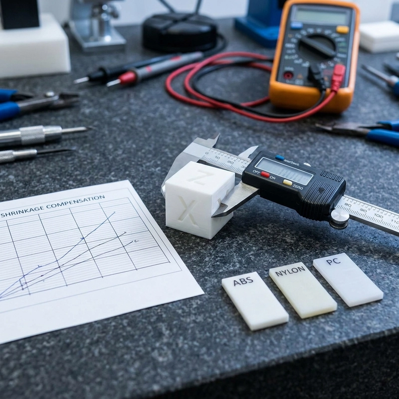
The source gives useful shrinkage references: PLA around 0.1-0.3%, ABS around 0.5-0.8%, and nylon around 0.8-1.5% in some workflows. These ranges are not universal. They show why large engineering plastic parts need compensation. A 50 mm calibration cube measured at 49.6 mm means about 0.8% shrinkage. That does not sound dramatic until the same error appears across a 300 mm housing or a row of mounting holes.
Shrinkage is not always uniform. Long thin panels curl. Thick corners hold heat. Holes print undersized because the bead path, thermal contraction, and slicer compensation all push inward. A belt or step calibration issue can make one axis different from another. I separate these problems during inspection: uniform scale error, local warping, hole error, and axis-specific machine error are not fixed the same way.
The broader measurement logic overlaps with Zesmir’s article on 3D printing accuracy parameters. For material choice before accuracy tuning, pair this article with engineering plastic 3D printing material selection.
Calibration, moisture, and heat control
Extrusion flow, steps, belts, nozzle condition, bed leveling, and chamber temperature all change part size. A printer that made accurate PLA parts may not hold ABS or PC parts without enclosure control. The source notes ABS bed temperatures above 80-90 C are often used, while PC usually needs a higher and more stable thermal environment. Use the material supplier and printer limits; do not copy a temperature from another machine and treat it as a process window.
Moisture is especially damaging for nylon and PC. Wet material can foam slightly, roughen the surface, weaken layer bonding, and make dimensions less repeatable. If a nylon part has inconsistent holes or a rough edge, I check drying and storage before blaming CAD. Calibration every 50-100 print hours or after changing consumables is a sensible reference from the source, but a failed tolerance check is also a reason to calibrate sooner.
Measurement should wait until the part is stable. A hot part coming off the bed is still moving. A nylon part may continue changing as it absorbs moisture. For functional assemblies, measure after cooling and after any required finishing, annealing, coating, or insert installation. The caliper reading before finishing may not be the size that reaches the customer.
Hole design and engineering plastic 3D printing dimensional accuracy
Holes are usually less accurate than outside dimensions. Small printed holes often need allowance, drilling, tapping, reaming, or heat-set inserts. If a shaft must rotate, do not design the CAD gap equal to the desired physical gap. A CAD gap is not the final physical gap. It will be affected by material, printer, orientation, cleanup, and finish.
Slot dimensions need the same caution. A slot that looks open in CAD may close slightly after shrinkage, while a thin wall beside the slot can curl outward. When the fit matters, I prefer printing a short tolerance strip with the same wall and slot geometry. It is cheaper than discovering after a full enclosure print that the clip, PCB, or rail will not seat.
For screw bosses, the safest route is often to print a pilot hole and machine or tap it afterward. For high-wear threaded assemblies, heat-set inserts or metal inserts may be better than printed threads. Critical datums can also be left with machining allowance. Hybrid printing plus CNC finishing may cost more per piece, but it can save a project where only two or three surfaces truly need tight tolerance.
Design choices that make accuracy easier
- Separate cosmetic faces from tolerance faces in the RFQ notes.
- Use ribs instead of thick solid blocks where warping is a risk.
- Avoid long unsupported flat panels when the material shrinks strongly.
- Add datum features that can be measured repeatably.
- Plan drilling, tapping, or CNC finishing for precision holes.
For neutral background on surface and dimensional measurement language, the NIST surface metrology project is a useful reference. It is not a 3D printing tolerance chart, but it helps keep inspection terms grounded.
What to send with an accuracy-sensitive RFQ
Send the STEP file if possible, not only STL. Mark critical dimensions, mating parts, hole functions, target quantity, material preference, and whether post-machining is acceptable. If you already printed a failed sample, include photos and measured values. Engineering plastic 3D printing dimensional accuracy improves when the supplier knows which dimensions matter and which dimensions can follow normal printed-part tolerance.
A good note does not need to be fancy. “These four holes fit an aluminum plate, this face is cosmetic, this rib can move a little” is already better than a silent STL. Engineering plastic 3D printing dimensional accuracy becomes a manageable manufacturing problem when the tolerance map is visible.