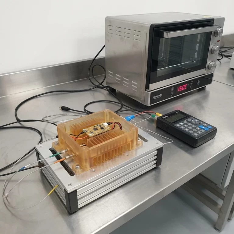
3D printed part strength is not fixed by dragging infill to 80 percent. I have seen parts with heavy infill fail at a thin boss, a sharp internal corner, a bad layer direction, or a screw hole that was never designed for torque. Strength comes from the load path first, then from material and settings.
Before changing slicer numbers, I ask one question: how is this part likely to fail? Bending, peeling between layers, stripping a thread, cracking around an insert, softening in heat, and wearing at a sliding face all need different fixes.
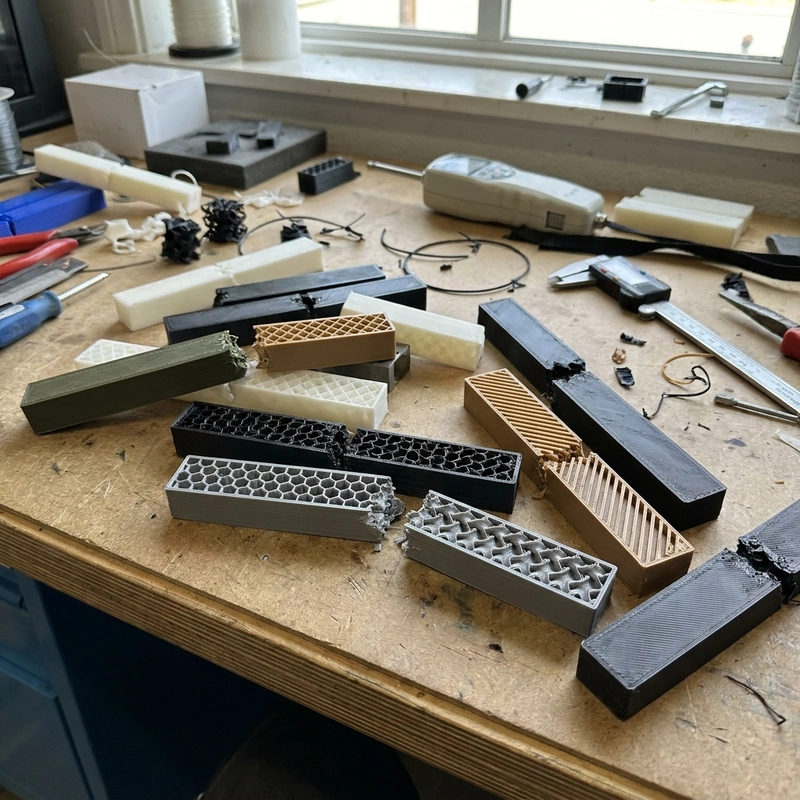
3D printed part strength begins with the weak plane
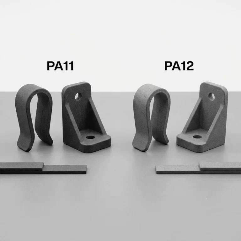
Layered parts are anisotropic. In FDM, the plastic path inside one layer is often stronger than the bond between layers. A hook printed upright may pull across layer lines. The same hook printed flat may put more continuous material along the load direction, but it may need support and may show a rougher side. There is no free orientation.
For a loaded bracket, handle, clip, or hinge, I mark the direction of the main force before slicing. If every orientation damages something important, splitting the model into two printed pieces and assembling them with screws, inserts, or adhesive can be stronger than forcing the whole part into one compromised print direction.
Infill is useful, but walls usually earn their keep first
Low infill around 10-20 percent may be enough for light display models or covers. Functional fixtures often sit somewhere around 40-70 percent, depending on shape and material. Heavy-duty parts may need 80-100 percent infill or a process change. Those ranges are starting points, not promises. A thin outer wall with high infill can still split because the stress enters the shell first.
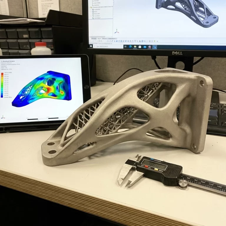
For many parts, extra perimeters, thicker bosses, ribs, fillets, and better screw-hole design do more than a big infill jump. Infill supports the shell and resists crushing, but it does not repair a bad corner radius or a screw placed too close to an edge.
| Failure sign | Likely cause | Better first check |
|---|---|---|
| Layer split | Load across weak layer bond | Orientation, temperature, cooling, material dryness |
| Boss cracks | Thin wall or sharp root | Boss diameter, fillet, insert design |
| Clip snaps | Brittle material or short flex zone | Material toughness and bend radius |
| Thread strips | Plastic thread overloaded | Metal insert or post-machining |
| Part bends too much | Low stiffness or thin section | Rib layout, material modulus, wall thickness |
Material choice changes the failure mode
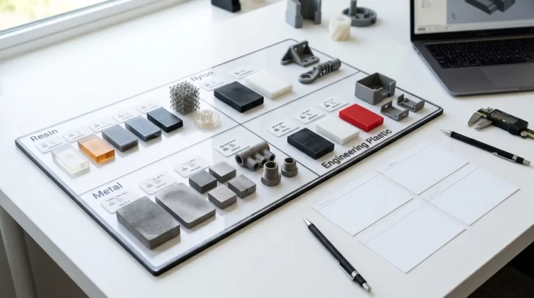
PLA is stiff and easy to print, but it can be brittle and heat-sensitive. ABS is tougher and more heat resistant, yet it needs better thermal control to avoid warping. Nylon, especially SLS or MJF nylon, is often useful for hinges, clips, gears, and wear surfaces because it has good toughness. Filled nylon can improve stiffness, but carbon or glass fiber can make impact behavior less forgiving and may wear FDM nozzles.
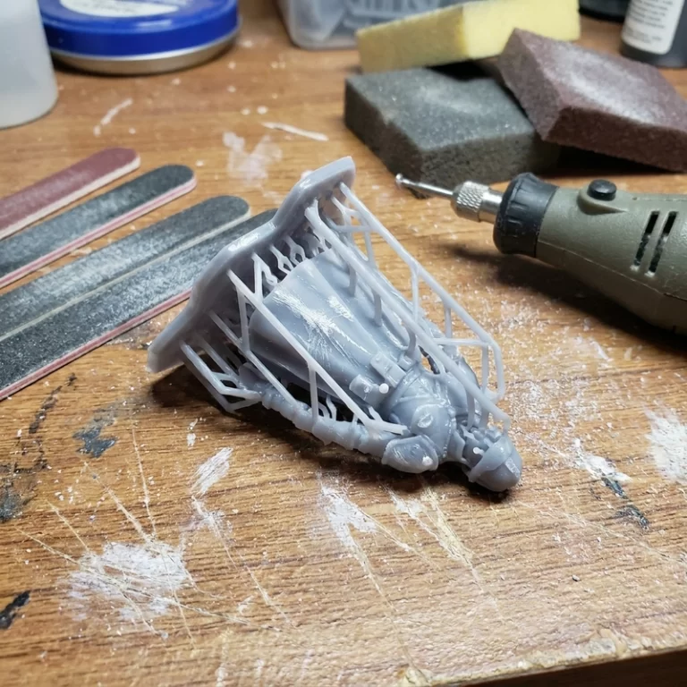
Resin parts need their own caution. A standard SLA resin can look beautiful and crack in a snap-fit test. Tough or ABS-like resins help, but they still do not behave exactly like molded thermoplastic. If a resin part must take screws, bending, or repeated handling, I want test coupons or a simplified feature sample before a full batch.
3D printed part strength checks before a functional order
I check load direction, wall thickness, layer direction, material, temperature exposure, screw torque, inserts, wear surfaces, and whether any critical feature can be machined after printing. For holes and assemblies, the companion article on 3D printed threads and inserts is worth reading. For file notes and tolerances, 3D printing file preparation keeps the RFQ from guessing.
When a part carries real load, generic material names are not enough. A neutral standards page such as ASTM’s additive manufacturing standards overview helps with vocabulary, but the usable answer still comes from testing the right material, in the right orientation, with the real failure mode in mind.
My rule is not glamorous: do not pay for more infill until the load path makes sense. 3D printed part strength improves fastest when orientation, wall design, material toughness, and layer bonding are handled together.
For a first sample, I like to break or overload a small sacrificial feature before trusting the full part. A short hook, a screw boss, a thin hinge strip, or a small tab printed in the same orientation tells more than a generic material claim. If the break follows the layer line, the setting or orientation needs attention. If it breaks at a sharp root, the CAD needs attention. If the screw strips before the part bends, the assembly method is the weak point.
Batch parts need the same caution. 3D printed part strength can drift when filament moisture changes, a nozzle wears, resin curing shifts, or powder-bed cooling varies. For a functional run, I would keep one reference sample, one process coupon, and a short inspection note. It is not paperwork for its own sake; it gives the buyer something to compare when the tenth part does not feel like the first.