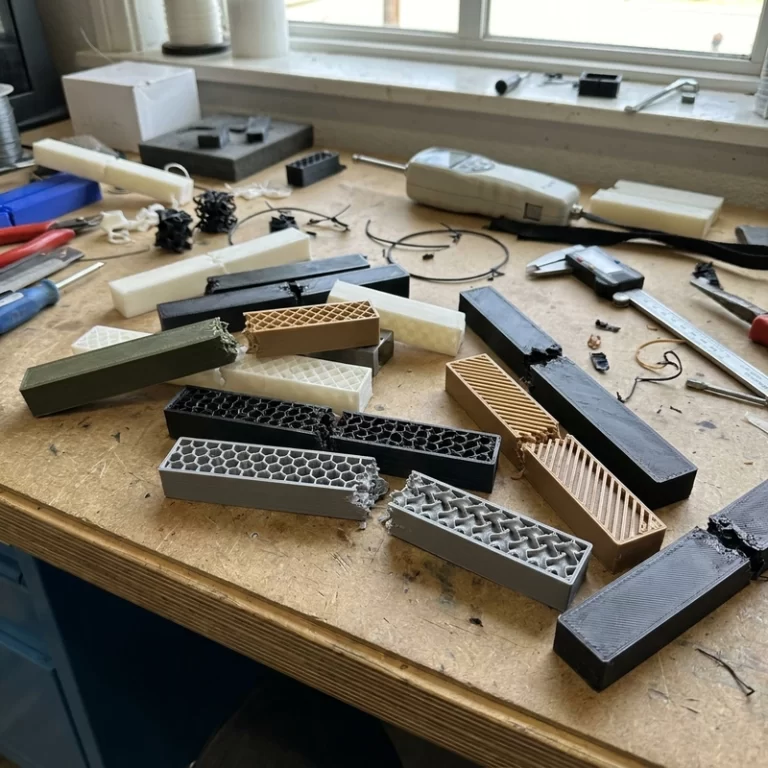
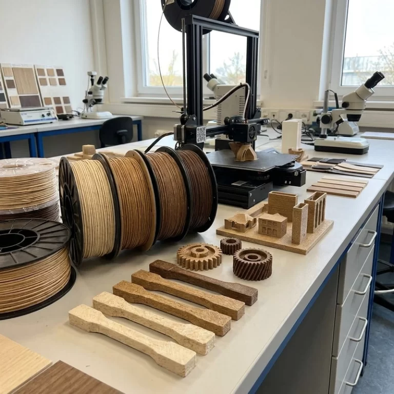
Fiber-reinforced 3D printing is useful when a plastic part needs more stiffness, better heat behavior, or lower weight, but it is not a magic upgrade. Carbon fiber, glass fiber, and continuous fiber systems all make the process less forgiving. The nozzle wears, the filament may clog, the part becomes directional, and layer bonding can decide the real strength.
When someone asks for “carbon fiber material,” I do not start with the material name. I ask where the load travels. If the fiber is not aligned with the load, the expensive material may only make the part stiffer in the wrong direction.
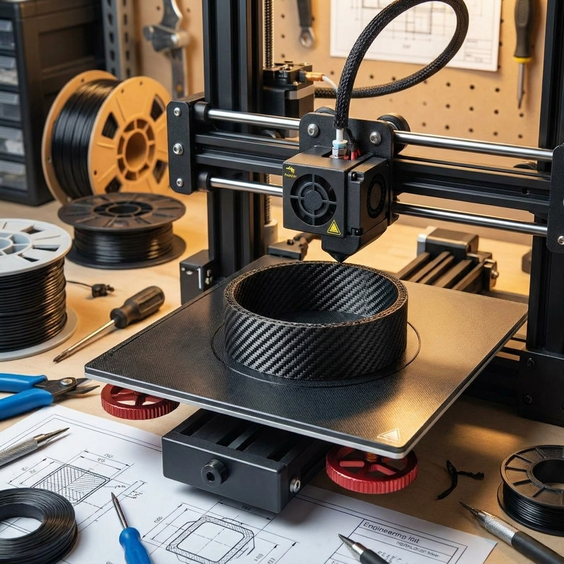
Fiber-reinforced 3D printing starts with fiber type
Chopped-fiber filaments mix short carbon or glass fibers into a polymer such as nylon, PETG, ABS, PC, or PEEK. They can increase stiffness and reduce some shrinkage, but the printed bead still behaves like an extruded thermoplastic. The source notes that short fibers around 0.2-0.5 mm are easier to process than longer fibers because they reduce clogging risk.
Continuous fiber printing is different. Long fiber is placed along a planned path, often with a separate matrix material. Strength can be high along the fiber direction and much lower across it. That means the fiber path is part of the structure, not a cosmetic infill pattern. A continuous fiber part can be excellent in tension along one axis and weak in a direction nobody checked.
Nozzle wear is a quality-control issue in fiber-reinforced 3D printing
Carbon and glass fibers are abrasive. A brass nozzle can wear quickly. A 0.4 mm nozzle drifting toward 0.45 mm sounds minor, but it changes line width, flow rate, corner sharpness, and hole size. The bad part is that nozzle wear is gradual. The first parts in a batch may measure differently from the last parts, and nothing dramatic happens to warn you.
Hardened steel, stainless steel, and tungsten carbide nozzles are common choices for reinforced filament. Exact life depends on fiber content, speed, temperature, feed rate, and nozzle size. I would rather schedule nozzle inspection and extrusion checks than wait until the surface gets fuzzy and dimensions wander.
| Issue | Likely cause | Practical control |
|---|---|---|
| Nozzle wear | Abrasive carbon or glass fiber | Hardened nozzle and regular line-width checks |
| Clogging | Fiber agglomeration, moisture, small nozzle | Drying, larger nozzle, stable material batch |
| Weak layers | Low heat, high speed, poor wetting | Temperature-speed coupon |
| Directional weakness | Fiber path misses the load | Orientation and load-path review |
| Brittle behavior | High filler or poor matrix bonding | Feature testing before batch printing |
Drying, speed, and bonding still matter
Fiber-filled nylon can print poorly when wet. Moisture creates bubbles, rough surfaces, and weaker bonding. Speed also affects bonding. The source included examples such as carbon-fiber PLA around 40-60 mm/s and 210-230 C, and carbon-fiber nylon around 50-70 mm/s and 240-260 C as starting windows. Those are not universal settings. They show the relationship: reinforced materials need enough heat and time for the matrix to bond around the fiber.
For continuous fiber parts, path planning matters as much as temperature. Tensile loads want fiber along the main force. Bending may need reinforcement near the outer stress zones. Torsion often benefits from +/-45 degree fiber directions. A simple “strong material” request is too vague for a composite part.
Fiber-reinforced 3D printing RFQ checks
I ask for base polymer, fiber type, expected stiffness, heat exposure, load direction, attachment points, quantity, critical dimensions, and whether the part sees fatigue or impact. For chopped-fiber FDM, the nozzle plan and drying condition matter. For continuous fiber, the fiber path should be discussed with the load path. The article on 3D printed part strength helps frame the failure mode, and high-speed FDM printing explains why flow and cooling cannot be ignored.
NIST additive manufacturing resources are useful for neutral background, but composite performance still needs part-specific review. My practical rule: use fiber to support the load path, not to decorate the material list. Fiber-reinforced 3D printing works when nozzle wear, drying, orientation, and bonding are controlled together.
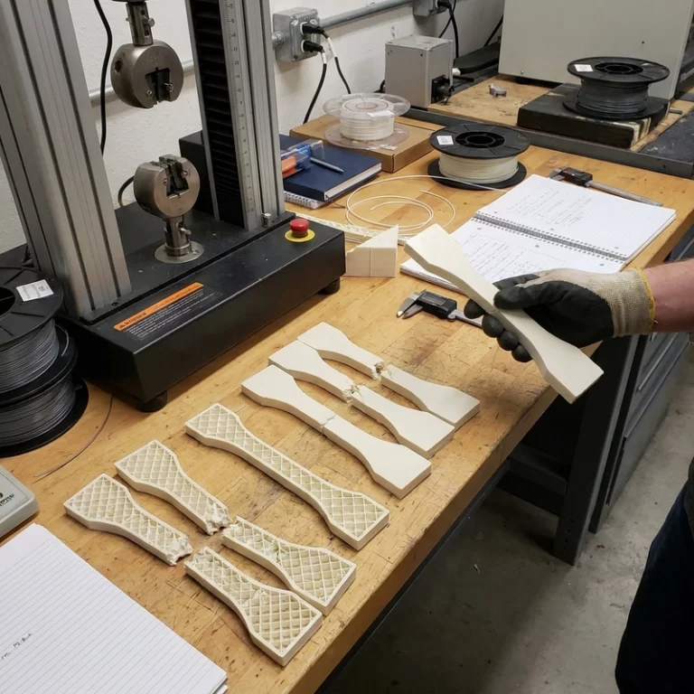
For a first coupon, I want it printed in the same orientation and with the same nozzle condition as the real part. A generic tensile bar printed flat may not say much about a bracket that fails at a vertical boss. If the part uses chopped fiber, I look for layer split, fuzzy edges, and hole drift. If it uses continuous fiber, I check whether the fiber path actually crosses the high-stress region instead of stopping short of the feature that carries the load.
Finishing also changes the decision. Fiber-filled materials can be abrasive during drilling or trimming, and rough fibers on a mating surface can wear against seals, cables, or bearings. I do not call fiber-reinforced 3D printing approved until the assembly surfaces, post-processing tools, and inspection points are part of the plan.
Storage is another small detail that turns into a large defect. Nylon-based reinforced filament should not sit open in humid air and then be judged as a failed material. Drying, sealed storage, and a short purge before the real build are part of the process when stiffness and surface quality matter.