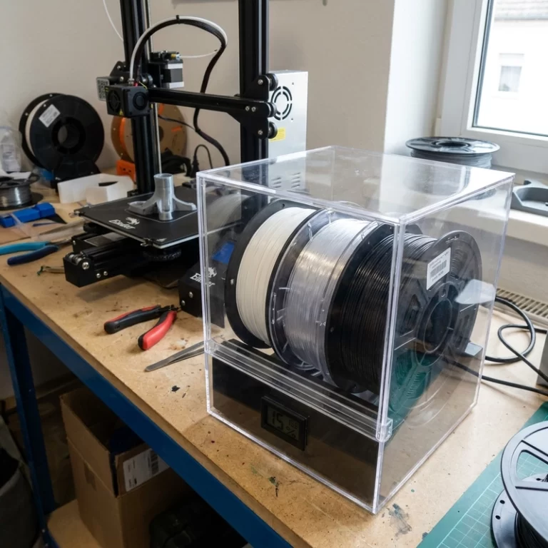
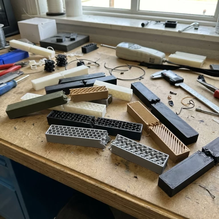
A long ABS print can begin lifting by less than a millimeter and still end with a distorted wall or nozzle collision. That failure is often blamed on retraction or the printer itself, while the real cause is uneven cooling. Diagnosing FDM warping therefore starts with the complete thermal path, not a single slicer setting.
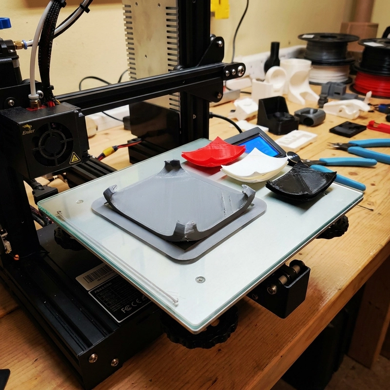
Warping is thermal stress, full stop. Hot filament goes down, cools, and shrinks. Bottom layers are anchored to the plate while upper layers keep pulling inward as they contract. Once that pull beats bed adhesion — and on a tall part the leverage gets worse with every layer — the edge curls. That’s why I treat FDM warping causes as a heat-flow problem, not a glue problem. ABS and nylon make this obvious on anything bigger than a benchy. PLA can still warp if the first layer is barely touching, the fan kicks in too hard, or the bed’s got a fingerprint right where a sharp corner sits.
FDM Warping Causes Start With Temperature Difference
Raising bed temperature can help, but it can also soften the first layers and create elephant foot without fixing the cause. Review actual bed-surface temperature, chamber stability, fan timing, drafts, part height and cooling rate together. Small chamber-temperature changes can materially affect ABS, so record the measured environment instead of relying only on controller setpoints.
A small PLA bracket on a textured PEI sheet might only need the Z offset nudged down 0.03 mm. A wide ABS electrical housing is a different beast — it might need the enclosure soaked at 45°C minimum, the fan locked at 0% for the first 10 layers, a 10 mm brim, and corner radii added in CAD before the first usable part comes off. A tall nylon component adds another wrinkle: the bottom stays warm near the heated bed while the upper section cools in open air, and that vertical temperature gradient alone can pull walls out of square. I’ve had nylon prints that looked perfect for the first 60 layers, then the whole thing bowed inward because I hadn’t blocked the draft from a window 4 meters away.
| Check point | What I look for | Practical correction |
|---|---|---|
| First layer | Round separate strands, gaps between lines, or over-squashed rough ridges | Re-level, adjust Z offset by 0.01–0.03 mm steps, confirm filament is slightly flattened against the plate |
| Bed surface | Finger oil, dust, old glue residue, glossy worn spots on PEI | Clean with the right solvent for that plate material — soap and water for textured PEI, IPA for smooth — before changing slicer settings |
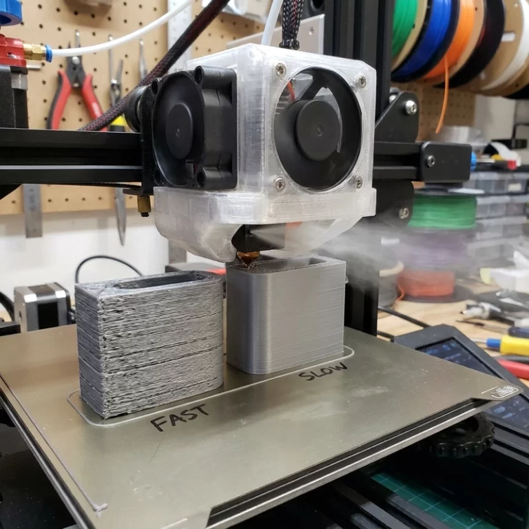
| Cooling fan | Corner lift that starts right after the part cooling fan kicks in | 0–10% fan for ABS and nylon; PLA can take 80–100% but delay the ramp-up on large flat parts |
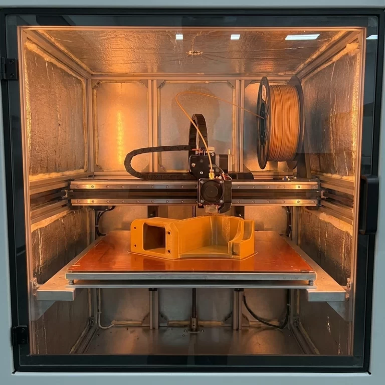
| Enclosure / drafts | Print behavior changes when doors, windows, or AC cycle on and off | Heat-soak enclosure to 40–50°C for ABS; block any air current that hits the build plate directly |
| Part geometry | Long flat strips, sharp 90° corners, thick solid blocks, large flat bottoms | Add corner radii, ribs for stiffness, brim or mouse ears, or split the part if assembly is acceptable |
FDM Warping Causes I Check Before Slicer Tweaks
The first layer is everything. If the nozzle is too high, filament lands as separate round ropes — looks clean from across the room, but contact area is maybe 40% of what it should be. If the nozzle is too low, the material smears, the extruder skips, and flow gets inconsistent. I want a first layer that’s continuous, slightly flattened, and boring. Boring is the goal.
Bed cleanliness is the boring check that saves hours. I once spent an entire afternoon chasing Z-offset numbers on a textured PEI sheet before I realized the plate had a thumbprint right where every test square’s corner sat. Finger oil beats a perfect slicer profile every time. Old glue stick residue can also create uneven contact — some spots grab hard, others barely hold. I clean the plate, then print a single-layer corner-risk square if the job matters, then change settings. Not the other way around.
Brims and rafts aren’t magic but they’re useful tools. A brim increases edge contact area and is often enough for moderate FDM warping causes on corners — I default to 5 mm for PLA and 10–15 mm for ABS on flat parts. Mouse ears on high-risk corners work when you can trim them after. A raft can help on difficult beds or difficult materials, but it eats time, filament, and leaves a rough bottom. I avoid rafts unless the part or material really demands that extra thermal buffer. The one exception: large flat ABS parts where even a 15 mm brim lifts. A raft with a 0.2 mm air gap has saved those more than once.
Material Behavior Behind FDM Warping Causes
PLA shrinks the least — roughly 0.2–0.5% — so small PLA parts usually behave. If PLA warps, I check bed adhesion, first-layer height, fan timing, and corner geometry before anything dramatic. The one PLA warping case that fooled me: a large flat base printed at 60°C bed with the fan at 100% from layer two. The corners lifted because the top was cooling and contracting faster than the bottom could resist. Dropping the fan to 60% for the first 20 layers fixed it — counterintuitive for PLA but the part was wide enough that the top layers were pulling hard.
PETG can adhere so strongly that a release layer is needed on smooth glass. ABS generally requires tighter enclosure control because cooling shrinkage builds stress at corners. Nylon adds moisture sensitivity and often needs drying before printing. A warp-free part can still fail through weak interlayer bonding, so dimensional stability and layer adhesion should be reviewed together.
For PC, ABS blends, carbon-fiber nylon, and high-temperature filaments, printer capability becomes part of the material choice. An open-frame machine can print small PC parts if the ambient temp is stable, but it won’t hold a large engineering-plastic housing flat across 200 mm. When FDM warping causes are material-driven, a wider brim just delays the failure. That’s not the printer’s fault — it’s a thermal envelope problem. If the machine can’t keep the material in a stable cooling range, either the part design changes or the process route changes.
Design Fixes for FDM Warping Causes That Beat Extra Glue
Sharp corners lift first because stress concentrates there. I add radii — even 2 mm helps — when the function allows it. Long flat strips are another red flag; a ribbed shape often does the same mechanical job with less shrinkage stress than a solid flat plate. Thick blocks hold heat and cool unevenly, while thin plates curl because the top and bottom surfaces are fighting each other across a short lever arm. The ugly truth: some warping problems are baked into the CAD file before the printer ever starts.
Splitting a large part can feel like defeat. But it’s often the cleaner engineering answer: smaller sections cool predictably, fit the bed better, and can be oriented to reduce stress concentration. The tradeoff is assembly labor and visible seam lines. For repeat jobs, I write suspected FDM warping causes into the job notes instead of trusting memory. For dimensional work, I also compare the finished part against engineering plastic dimensional accuracy, because a flat-looking print can still be out of tolerance by half a millimeter after cooling.
My Troubleshooting Order for FDM Warping Causes
- Clean the bed and verify the first layer is actually bonded — not just visually present, but squished into the surface texture.
- Confirm Z offset and bed mesh before changing material settings. A 0.02 mm offset error can be the entire problem.
- Add a brim or mouse ears to the corners that lift first. Start at 5 mm and go wider if needed; 10–15 mm for ABS on large flats.
- Reduce aggressive cooling for ABS, nylon, and other high-shrink materials. 0–10% fan on the first 10 layers, then ramp up only if bridges or overhangs demand it.
- Use an enclosure or block drafts, especially for large parts. Heat-soak the chamber to at least 40°C for ABS before starting.
- Add corner radii, reduce long flat spans with ribs, or split the part when geometry is the real driver.
- If the material keeps fighting the machine, switch materials or change the process instead of chasing one more slicer trick. Some parts are just not meant for FDM in that geometry at that scale.
One caution on enclosures: they stabilize chamber temperature and block drafts, which is essential for ABS and nylon. But FDM printing can generate fumes and ultrafine particles depending on the material. I reference the ISO/ASTM 52900 additive manufacturing vocabulary for standard terminology and follow the filament supplier’s SDS for ventilation and handling. An enclosure is a process tool, not an excuse to skip air quality management.
The rule I’ve settled on after too many failed prints: FDM warping causes are almost never one setting. Hold the first layer. Reduce the thermal gradient between bottom and top. Make the geometry less eager to curl. Choose a material the machine can realistically control. If those four things aren’t true, the part might print for a while — then the corner tells the truth.