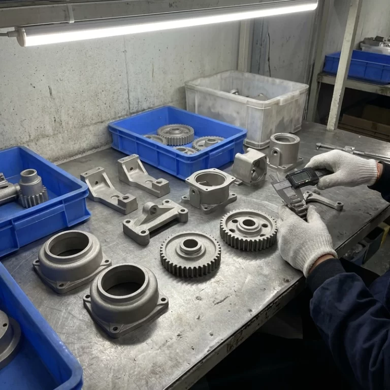
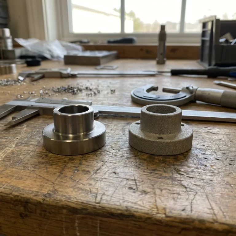
SLM defects are rarely explained by one parameter. Cracks, internal porosity and distortion can appear in the same production workflow, but each points to a different combination of geometry, powder condition, atmosphere, energy input, support design and thermal history. A useful diagnosis starts with the defect signature instead of assuming that one “golden recipe” will fit every part.
When I train new operators, the first thing I tell them is: stop chasing the perfect parameter set. The machine does not care about your spreadsheet. What matters is whether you can look at a pore shape under the microscope and know whether the powder was wet, the hatch spacing was too wide, or the gas flow was blowing spatter back into the melt pool. That takes time on the floor, not time in a simulation.
Why SLM Metal 3D Printing Defects Show Up in the First Place
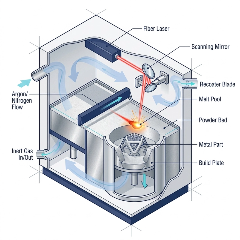
SLM is a brutal thermal environment. You are shooting a 200-400 watt laser at a 30-micron powder bed, creating a melt pool that hits 1600+°C in microseconds, then watching it freeze in milliseconds while the layers underneath are still cooling from the last pass. The thermal gradient between the melt pool and the solidified bulk can exceed 10⁶ K/m in some alloys. That is not an exaggeration — I have seen the pyrometer traces.
Every new layer re-melts a bit of the old layer. Every scan track overlaps its neighbor by some fraction. If that overlap is wrong, if the energy density drifts, if the powder spread was uneven because the recoater blade has 800 hours on it and nobody checked — you get voids. Sometimes round gas pores from trapped argon. Sometimes jagged lack-of-fusion cavities that follow the scan pattern like a fingerprint. Sometimes cracks that do not appear until you cut the supports and hear that awful ping.
The coupled variables are not abstract theory. On any given Monday, I am checking powder moisture content, recoater condition, chamber oxygen (targeting below 300 ppm for titanium, below 500 ppm for steel), gas flow uniformity, filter saturation, laser window cleanliness, and baseplate flatness — before I even look at the parameter file. Miss any one of those and you are debugging ghosts.
The 7 Defect Types I See Most Often
| Defect type | What I see under scope / CT | Root mechanism | When it bites hardest |
|---|---|---|---|
| Gas pores | Round voids, 10-100 μm, scattered or clustered | Trapped shielding gas, powder moisture, oxide film vaporization — gas cannot escape before the puddle freezes | Wet powder, poor chamber purge, spatter falling back into the melt zone |
| Lack-of-fusion pores | Irregular, elongated voids, 50-500 μm, aligned with layer lines or scan tracks | Energy too low or scan overlap too narrow — powder does not fully melt into the previous layer | Pushing speed too high, hatch too wide, thick layers, worn recoater leaving uneven powder |
| Shrinkage pores | Dendritic or irregular cavities, often at the end of solidification fronts | Liquid-to-solid volume contraction with no feed metal available | Fast cooling rates, constrained geometry, poor melt pool fluidity |
| Hot cracks | Intergranular, branching networks, concentrated at corners and section transitions | Thermal strain + solidification shrinkage exceeds the material’s hot strength; low-melting phases at grain boundaries make it worse | Nickel superalloys, high-carbon steels, thick-to-thin transitions, no preheat |
| Residual-stress cracks | Part builds clean, then cracks hours later — after support removal or during storage | Locked-in thermal stress releases when the baseplate constraint is removed | Large Ti64 or 17-4PH parts, no stress relief, aggressive support removal |
| Distortion | Warped base, curled edges, hole positions off by 0.2 mm or more | Non-uniform cooling and asymmetric stress accumulation pull the part out of shape | Thin walls, long spans, weak support structures, single-direction scan strategy |
| Balling / surface roughness | Bead-like droplets 50-200 μm on the surface, rough finish | Melt pool becomes unstable and breaks into droplets instead of wetting and spreading | Excessive energy density, poor wetting, focus offset, gas turbulence over the powder bed |
Porosity: Gas Pores vs. Lack of Fusion — Two Completely Different Fixes
“Porosity” is not a complete diagnosis. Rounded pores can indicate trapped gas, while irregular or lack-of-fusion-shaped voids point toward insufficient melting, poor overlap or contamination. Raising laser power without classifying the pore shape can introduce new defects, so visual or CT evidence should be reviewed before changing parameters.
Round gas pores mean something is outgassing or trapping shielding gas. My go-to checklist: powder drying (Ti64: 120°C for 3 hours minimum in vacuum; 316L: 80°C for 2 hours), powder sieving through 200 mesh to break up agglomerates, chamber purge quality, oxygen reading trend over the first 20 layers, and spatter pattern on the camera. I once chased a gas porosity problem for four builds before realizing the argon supply line had a slow leak — the O₂ sensor lagged enough that the first 15 layers printed at 800+ ppm before the alarm triggered. Fixed the fitting, porosity gone.
Lack-of-fusion porosity looks different — jagged, irregular, and it follows the scan pattern. This is an energy delivery problem. Reduce scan speed, bump power, tighten hatch spacing, or drop layer thickness. On a 316L gear job that came in at 5% internal porosity, we went from 200 W / 1200 mm/s / 0.10 mm hatch to 220 W / 1000 mm/s / 0.08 mm hatch and cut it to 0.3%. That recipe is not universal — your powder supplier, machine calibration, and part geometry all matter — but the logic is always the same: increase melt pool overlap and dwell time without crossing into overmelting and balling.
Scan strategy plays into this more than most parameter sheets admit. Rotating the scan vector 67° between layers (not 90° — 90° can stack weak planes on four-fold symmetry parts) gives gas more escape paths and breaks up texture alignment. For thin walls under 1 mm, I run contour-first with about 15% higher contour power than infill, and for deep blind holes I use a spiral-inward path so gas is not trapped at the bottom with nowhere to go.
Cracking: It Is Almost Always Thermal Before It Is Mechanical
A part can test at 900+ MPa tensile and still crack at the support interface if thermal stress was never managed. Hot cracking happens in the solidification range — the mushy zone where the material has zero ductility and any strain tears it open. Residual-stress cracking is sneakier: the part looks perfect on the build plate, then cracks three hours after support removal, or worse, during the customer’s first pressure test.
Preheating is the first lever. For 316L I run 150-200°C baseplate. Ti64 needs 250-300°C. Inconel 718 needs at least 300°C and I have pushed it to 400°C on thick-section parts where every previous attempt cracked at the flange radius. These are starting points. I have had Ti64 builds crack at 280°C on one machine and print flawlessly at 260°C on another — same powder batch, different machine architecture. The thermal field inside the chamber is not uniform and your preheat setpoint is not the actual temperature at the part surface 200 layers up.
Cooling rate matters just as much. My personal rule: crack-sensitive parts stay in the chamber under argon for a minimum of 8 hours after the build finishes. Large Ti64 structural parts get 12 hours. I have broken this rule twice and paid for it both times — once with a 17-4PH manifold that cracked audibly while I was removing supports, once with an Inconel impeller that passed dye penetrant at the shop but cracked during HIP because the subsurface stress was already there.
Heat treatment must be specified by alloy, part condition and acceptance requirement. Stress relief can reduce residual stress; hot isostatic pressing may be considered for fatigue-critical parts when the material route and inspection plan justify it. Temperature, pressure, time and atmosphere should follow the qualified material procedure, supplier data and relevant standards such as ASTM F3301 rather than a universal shop setting.
Parameter Windows That Actually Matter on the Floor
| Control point | What I actually use | Why I check it | What goes wrong if you ignore it |
|---|---|---|---|
| Powder size | 15-45 μm D50, sieved through 200 mesh before every job | Flowability and spread uniformity — large particles or agglomerates wreck layer consistency | Over-reused powder shifts the PSD finer, increases oxygen pickup, changes flow |
| Powder reuse | Cap at 10 cycles for structural parts, 5 for fatigue-critical; always dry + sieve before reuse | Controls oxidation and satellite-particle buildup | Critical aerospace parts need virgin powder or strict refresh ratio — do not gamble |
| Chamber oxygen | <300 ppm for Ti and Ni alloys, <500 ppm for 316L | Oxidation, spatter generation, and embrittlement all scale with oxygen | Titanium at 600+ ppm will give you brittle parts and a discolored surface that no amount of HIP can fix |
| Shielding gas | Argon 99.999% for reactive alloys; 99.99% minimum for steel | Protects the melt pool — but flow pattern matters more than purity number | Poor gas flow leaves spatter on the powder bed; too much flow disturbs the powder |
| Hatch spacing | 0.08-0.12 mm; I default to 0.09 mm for Ti64 precision parts | Controls melt pool overlap — the single most sensitive parameter for lack of fusion | A wide hatch spacing combined with thin Ti64 layers can increase lack-of-fusion risk, but the result depends on laser power, scan speed, overlap strategy, powder condition, equipment and validation method |
| Layer thickness | 0.03-0.05 mm for precision; 0.04 mm is my Ti64 sweet spot | Energy penetration depth must exceed layer thickness by ~30% | Thicker layers save time but demand more power and tighter hatch — test coupons first |
| Edge parameters | Edge power +10-15%, hatch spacing -20% in contour zones | Edges cool faster than bulk — they need extra energy to avoid lack of fusion | Overcompensating edge power causes roughness and stress concentration at the worst possible location |
| Support density | 30-50% in crack-prone zones; 40-60% around holes and edges | Restrains distortion and conducts heat away from the part | Over-built supports scar the surface and can crack the part during removal — support design is a separate skill |
Single-variable testing is slow and boring and it is still the only method I trust. When porosity shows up in a new geometry, I print a 10 mm cube coupon changing exactly one parameter at a time, section it, and look at it under the scope. Changing power, speed, hatch, and support design all at once tells you nothing about which one actually fixed the problem — and you will repeat the same mistake on the next job.
Melt-Pool Monitoring: What the Camera Is Actually Telling You
CT and metallography are gold-standard, but they are post-mortem tools. By the time the CT report lands on your desk, you have already burned powder, machine hours, and post-processing capacity on a bad part. Melt-pool monitoring gives you live signals — if you know which ones to ignore and which ones to act on.
The raw temperature number is nearly useless on its own. What I watch: sudden jumps in melt-pool area (more than 20% frame-to-frame means something changed — power instability, speed fluctuation, or the laser hit a spatter particle), sustained drops in melt-pool depth (below ~30 μm for more than a few frames screams lack of fusion), temperature fluctuation amplitude (cycling above ±100°C says your energy input is unstable), and spatter density trends (continuous directional spatter usually means wet powder; violent random spatter usually means focus offset or gas turbulence).
I set three action levels on our monitoring system. Level 1 — log it, review after the build. Level 2 — auto-adjust laser power within a narrow ±5% validated window (this catches gradual drift from filter loading or window fogging). Level 3 — pause the build. I trigger Level 3 when I see repeated crack-like thermal signatures, because one cracked layer cascades into a scrapped part and more wasted powder on top of it. The trap to avoid is false confidence: your monitoring system needs to be trained on your machine, with your powder, correlated against your own CT and cross-section data. A generic model from the sensor vendor will miss your specific failure modes.
A Real Debugging Session: Ti64 Aerospace Bracket
This one stuck with me. A Ti64 aerospace bracket — wall thickness ranging from 1.2 mm to 6 mm, internal channels, mounting flanges with tight hole position tolerances. First build: 8% internal porosity on CT, edge cracks visible to the naked eye, hole positions off by 0.2 mm, and we threw away nearly 30% of the powder because of oxidation discoloration in the overflow. The production manager wanted to scrap the whole job and switch to CNC from billet.
I dug into each problem separately instead of chasing a magic parameter set. The porosity was mostly lack-of-fusion at the thin-to-thick transitions — the scan strategy was using the same parameters everywhere and the thin walls were cooling too fast for proper overlap. The edge cracks were thermal: no preheat, chamber oxygen hovering around 600 ppm (our sensor calibration had drifted), support density at 20% with sharp break-off points. The powder waste was easy — the drying oven timer had failed and nobody noticed for two shifts.
The fix package, after two weeks of coupon testing: power 280 W, scan speed 800 mm/s, hatch 0.09 mm, layer 0.04 mm. Chamber oxygen below 250 ppm verified with a freshly calibrated sensor. Baseplate preheat at 250°C. 12-hour chamber cool-down before opening. Support density bumped to 40% with tapered break-off geometry. Powder dried at 120°C for 3 hours and sieved through 200 mesh. Stress relief at 650°C for 2 hours, then HIP at 920°C / 100 MPa / 2 hours.
Third build: density 99.8%, zero visible cracks, dimensional deviation within ±0.08 mm, tensile 920 MPa, impact 35 J, powder waste under 10%. The point is not the numbers — the point is the sequence. Classify the defects, fix powder and atmosphere first (they are the cheapest problems to solve and the most common root cause), then tune energy and support, then validate with heat treatment. Skip a step and you will chase your tail for weeks.
If you are dealing with a similar bracket or structural part and want to compare notes on printability, our team handles these kinds of metal AM production jobs regularly — geometry review, parameter development, and full inspection package. For a broader look at how different AM technologies compare before you commit to SLM, our HP MJF technology breakdown covers the polymer side of production printing.
Inspection Checklist I Actually Use
- Print a test coupon every time you change material batch, layer thickness, scan strategy, or heat treatment cycle. No exceptions. A 10 mm cube costs 15 minutes of machine time and saves weeks of failure analysis.
- Metallographic cross-sections are cheap compared to CT. Use them to separate gas pores, lack-of-fusion, and crack morphology before ordering a full CT scan.
- X-ray or CT for internal porosity mapping on any part with closed channels, sealing surfaces, or fatigue loading. Surface inspection alone will miss the subsurface lack-of-fusion that kills fatigue life.
- CMM or 3D scanning for distortion — measure hole positions, flatness, and critical dimensions before machining allowance is consumed.
- Log everything: powder batch number, reuse count, drying time/temperature, chamber oxygen trend, baseplate temperature, laser power, scan speed, hatch spacing, layer thickness, support settings, post-processing parameters. When a build fails six months from now, this log is the only thing that will tell you why.
- Validate tensile, hardness, density, and surface roughness on the first article before signing off for batch production. One good coupon does not prove the process is stable.
What to Put in an SLM RFQ So the Supplier Does Not Ghost You
I review RFQs from the other side of the table now, and most of them are missing the information that actually determines whether a part is printable. If you want a real quote instead of a placeholder number, include: alloy grade and specification (not just “titanium” — which titanium?), drawing with tolerances, critical surfaces and load direction clearly marked, expected heat treatment condition, inspection requirements (CT? dye penetrant? tensile coupons?), quantity and lead time, density target, and surface roughness requirements. If the part has walls thinner than 0.5 mm, deep channels with aspect ratio above 8:1, sealing surfaces, or fatigue-loaded features — flag those on the drawing. Those details determine whether the job is SLM-only, SLM plus CNC post-machining, or SLM plus HIP plus final machining. A clear RFQ saves everyone two weeks of back-and-forth email.
SLM defects are not solved by changing one number in a parameter file. Gas pores, lack of fusion, hot cracking, stress cracking and distortion leave different signatures. The defensible workflow is to classify the defect, check powder and atmosphere, review energy input and overlap, control the thermal cycle, validate with inspection data and document the approved settings before production release.