
A slicer can open an STL and still give you the wrong part. Scale may be off, a thin wall may exist only as a surface, or a repair tool may close a hole that was meant to stay open. Good STL file preparation is less about chasing a “perfect” mesh score and more about checking what the triangles actually represent before the file reaches quoting or production.
I use STL for print geometry, but I do not treat it as a complete manufacturing drawing. It is a surface mesh. It does not reliably carry units, material, tolerances, assembly intent or revision history. Those details have to travel with the file.
STL File Preparation Starts With Revision, Scale and Units
1. Remove old revisions from the upload package
Do not send three files called “final” and expect the reviewer to identify the newest one from the timestamp. Put the revision in the filename and keep obsolete geometry outside the RFQ folder. If several parts belong to one assembly, use stable part numbers that also appear on the drawing or bill of materials.
2. State the units and one known dimension
STL coordinates are numbers without a dependable unit declaration. A model exported in inches can be interpreted as millimetres, and the geometry will still look valid on screen. State the unit system in the RFQ notes and include one known outside dimension as a quick scale check. That simple reference catches more trouble than a complicated filename.
Check Mesh Topology Before You Increase Resolution
3. Find open edges, non-manifold geometry and inverted faces
A printable solid normally needs an unambiguous inside and outside. Open boundaries, overlapping faces, self-intersections and edges shared by an unexpected number of triangles can confuse repair software and slicing. Reversed normals may turn a local region inside out. Automatic repair is useful, but I always compare the repaired model with the original around holes, thin slots, text and internal channels.
4. Separate intentional parts from accidental shells
A single STL may contain disconnected shells. Sometimes that is intentional, such as captive geometry or a multi-body display model. Sometimes it is a floating fragment left from a CAD operation. List the expected part count and inspect every isolated shell. Small debris can create unwanted print islands; merged components can make an assembly impossible to separate.
Tessellation Should Follow the Geometry, Not a Universal Number
5. Use enough triangles for curves without making a uselessly heavy file
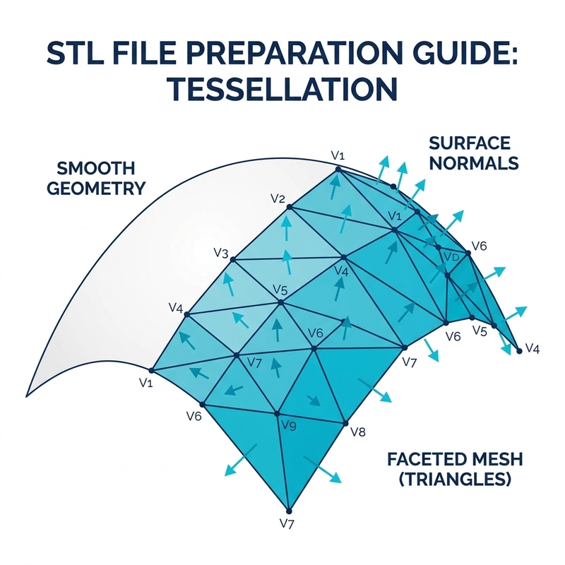
Coarse tessellation turns cylinders into visible polygons and can flatten small fillets. Excessively fine tessellation creates a large file without adding printable detail. The export tolerance should reflect part size, visible curvature and the intended process. There is no single chordal value that suits a tiny jewellery model, a large fixture and a metal impeller.
Zoom in on circular holes and customer-facing curves after export. If the facets are visible at the scale that matters, revise the export. If flat faces are split into a huge number of tiny triangles with no geometric benefit, reduce the mesh density. Binary STL is normally more compact than ASCII for the same geometry.
STL File Preparation Does Not Replace Design Review
6. Check wall thickness and fragile features in the actual process
A watertight mesh can still describe a wall that is too thin to print, clean or handle. Pins, embossed text, knife edges, drain holes and snap features need process-specific review. SLA resin, powder-bed nylon, FDM plastic and metal printing do not share one minimum feature rule. Use the 3D printing design guidelines to review geometry after the mesh itself is clean.
7. Inspect cavities, escape paths and moving clearances
Closed internal cavities may trap uncured resin or powder. Moving parts printed together need room for process variation and cleanup. A clear gap in CAD may close after printing, curing, blasting, dyeing or coating. Mark internal passages that must remain open and identify surfaces that cannot accept support marks.
8. Keep STEP and drawing data when dimensions matter
For engineering parts, send STEP with the STL when possible. STEP gives the reviewer cleaner access to analytic geometry, holes and faces if machining or measurement is required. Add a PDF drawing for critical dimensions, threads and inspection points. The STL remains useful for print geometry; it just should not carry every responsibility by itself.
A Short STL File Preparation Check Before Upload
- Confirm the current revision and remove obsolete files.
- State millimetres or inches and provide one known dimension.
- Check open boundaries, normals, intersections and disconnected shells.
- Compare repaired geometry against the original CAD model.
- Review curved surfaces at the intended physical size.
- Check thin features, cavities, escape paths and moving gaps.
- Send separate files for separate parts unless captive geometry is intentional.
- Include STEP, drawings, quantity, finish and inspection notes when relevant.
The Library of Congress description of the STL format family is a useful neutral reference for what the format contains: triangular facets, vertices and outward normals. It also makes the limitation clear. STL is a mesh format, not a full manufacturing specification.
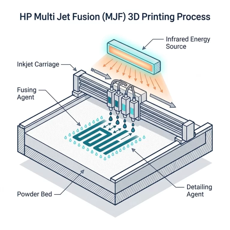
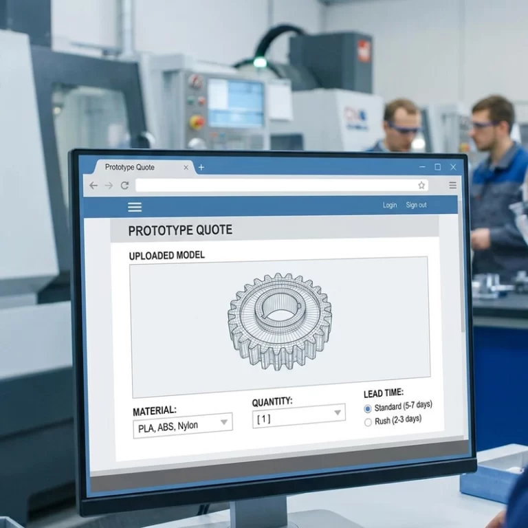
Once the mesh passes this STL file preparation check, use the 3D printing RFQ checklist for quantity, material, finish and tolerance notes. The process overview can help when SLA, nylon, FDM, metal or hybrid manufacturing is still undecided.

2 Comments