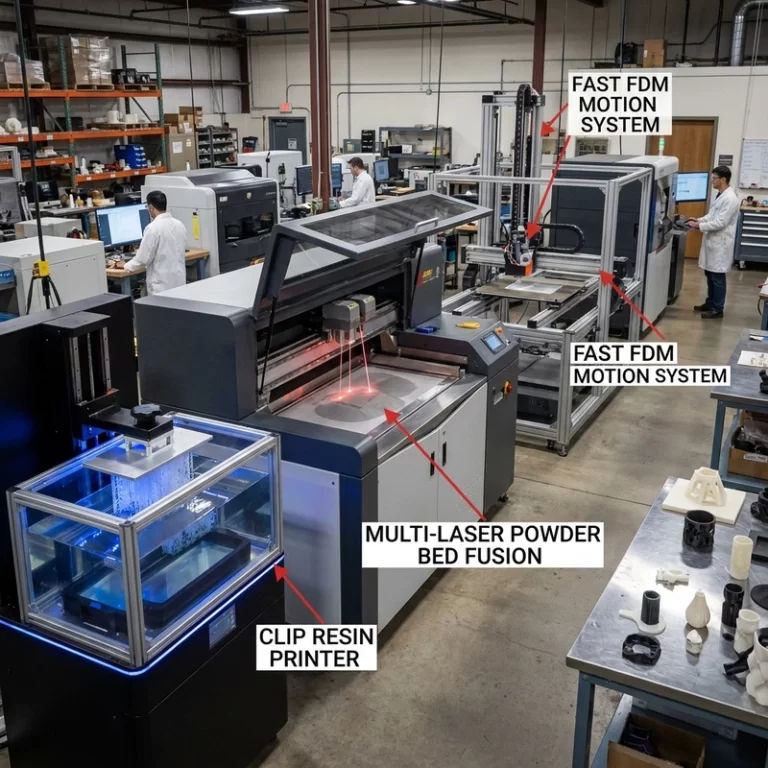
3D printing design guidelines are not a decoration at the end of a CAD job. They decide whether the file prints cleanly, whether the part fits after cleanup, and whether the quote you receive is close to the final manufacturing cost. I normally start with the boring checks first: wall thickness, small holes, clearances, support contact faces, material behavior, and which dimensions actually matter.
A CAD model can look perfect on screen and still be a rough manufacturing file. Thin ribs may survive in SLA but crack during support removal. A nylon hinge may print in MJF or SLS but bind after powder removal. A metal part may need machining stock on datum faces before it can be assembled. The file may still be printable. It just may not work the way the drawing expects.
3D Printing Design Guidelines Start With the Part Function
The first question is not “can the printer make it?” A surprising number of parts can be printed once. The better question is what the part has to do after printing. I mark the model into zones before changing anything: cosmetic faces, support-safe faces, assembly interfaces, screw locations, sealing surfaces, flexible areas, and surfaces that can be sanded or painted.
Wall Thickness Is a Manufacturing Choice, Not Just a Number
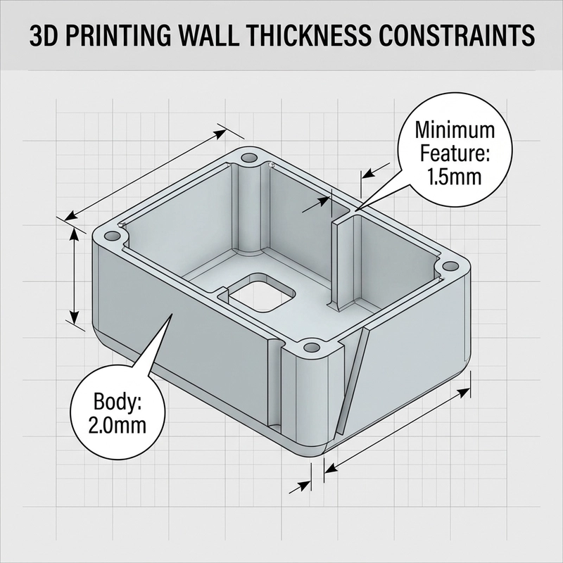
Minimum wall thickness depends on process, material, part size, orientation, and post-processing. I avoid quoting one universal value because it creates false confidence. SLA can show fine detail, but very thin resin walls may warp or become brittle after curing. FDM walls need enough width for extrusion paths and layer bonding. MJF and SLS nylon need enough section to survive depowdering and handling.
When a model has thin covers, tall ribs, small pins, hollow shells, or sharp transitions, the wall check should happen before price discussion. A quote based on a fragile model often changes after file review. If you want more predictable quoting, pair these 3D printing design guidelines with a clean file package from our STL file preparation guide.
Clearance and Tolerance Need Room for the Real Process
A CAD gap is not the final physical gap. Resin shrinkage, powder-bed cooling, FDM bead width, support cleanup, dyeing, painting, sanding, and machining all change fit. I do not trust a moving joint or snap fit until the clearance is matched to the material and process. A hinge designed for a machined plastic part may lock up when printed in resin. A sliding nylon feature may need more clearance than the screen suggests.
Critical fits should be called out in the RFQ notes. If a hole only needs to look like a hole, say that. If it carries a screw, receives a brass insert, aligns with another part, or needs reaming after printing, say that too. Tolerance problems often start as missing file context, not printer failure.
Support Direction Can Change the Best Design
Support planning is where many nice-looking models become expensive. In SLA, supports leave contact marks and can pull delicate features during removal. In FDM, support under shallow overhangs may create rough faces. Powder-bed nylon avoids separate support structures, but trapped powder and fragile unsupported details still matter.
I look for a safe support side before I look for the fastest print orientation. For a painted figurine, that may be the back of the hair or underside of the base. For an electronics housing, it may be the inside wall rather than the front texture. Good 3D printing design guidelines should tell the supplier where scars are acceptable and where they are not.
Small Holes, Threads and Inserts Need a Plan
Small holes close up more easily than designers expect. Resin can cure slightly into a hole. Powder can remain in a blind feature. FDM can leave rough circular geometry because the nozzle path is not a drilled hole. I would rather see a pilot hole and a tapping note than a fake perfect thread modeled into a file that cannot hold load.
For threaded assemblies, separate the question into three routes: print the thread for light-duty checking, print a pilot hole and tap it, or design for a heat-set or press-fit insert. Each route affects wall thickness around the boss. A thin screw tower may print, then split when the insert is installed. That failure is a design issue, not just a printing issue.
Material Choice Belongs Inside 3D Printing Design Guidelines
Material is not a dropdown after the model is finished. A resin chosen for smooth detail may not be the right choice for a snap-fit tab. PA12 nylon may be better for functional flexibility, but surface texture is different from SLA. FDM can be cost-effective for large fixtures, but layer direction and warping have to be accepted or designed around.
For process terminology, neutral references such as NIST additive manufacturing help keep the vocabulary grounded. A reference does not qualify a part by itself, but it prevents design and process discussions from drifting.
A Short RFQ Checklist Before You Upload
Before sending a file for quote, I would check these nine items:
- Export both STEP and STL when possible, especially for mechanical parts.
- State the real unit system and final size.
- Mark cosmetic faces and surfaces that cannot take support marks.
- Call out critical dimensions instead of treating every edge as critical.
- Check wall thickness around ribs, covers, screw bosses and hollow shells.
- Give clearance expectations for moving parts, hinges, snap fits and sliding areas.
- Tell the supplier if holes are decorative, tapped, reamed or fitted with inserts.
- State the surface requirement: raw, sanded, dyed, painted, polished or machined.
- Include quantity, packaging needs and whether a first sample must be approved.
This is where 3D printing design guidelines become useful for real buying work. They reduce quote revisions, but they also protect the part from being optimized for the wrong thing. A cheap print that cannot assemble is not cheap. A beautiful print with the wrong material is still the wrong part.
What I Would Fix Before Changing the Process
When a model looks risky, I do not jump straight from SLA to MJF, or from FDM to CNC. I first check whether the geometry can be made more honest: thicker bosses, larger drain holes, less aggressive overhangs, more clearance, added fillets, split parts, or a clear machining allowance. For nylon functional parts, the HP Multi Jet Fusion MJF guide is a useful next read.
The practical rule is simple: upload the file only after you know what must fit, what may be cosmetic, and what can be adjusted. That gives the quote a much better chance of matching the part you actually need. When the process is still open, the custom 3D printing service process map is a useful way to compare resin, nylon, FDM, metal and hybrid manufacturing routes before the RFQ.