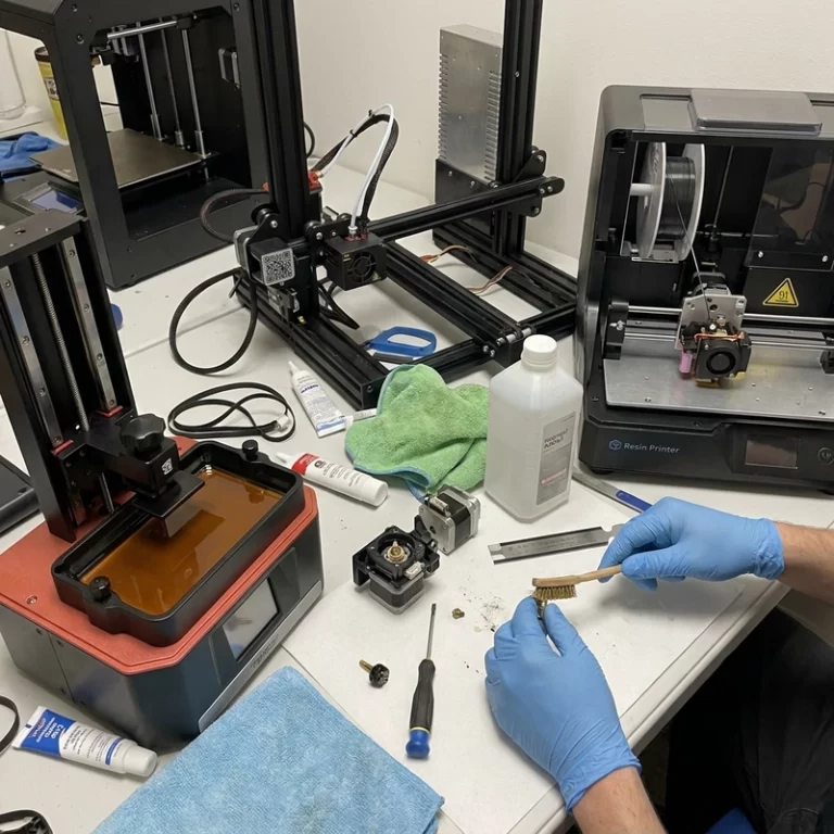
High-speed additive manufacturing is not the same as moving the nozzle, laser or build platform faster. Real throughput is the number of acceptable parts that come out after cooling, cleaning, support removal, curing, depowdering, machining, inspection and rework. I care less about headline speed and more about accepted output per shift.
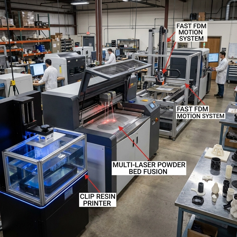
The bottleneck changes by process. FDM may be limited by melt flow, cooling, acceleration or vibration. Resin printing may be limited by exposure, peel mechanics, oxygen inhibition, resin viscosity or post-curing. Powder bed fusion may be limited by laser scan time, recoating, heat accumulation, powder cooling or downstream support removal. A process becomes faster only when the real bottleneck moves.
High-Speed Additive Manufacturing Has Hidden Bottlenecks
Part mix matters. A large solid tool, a small figurine batch, a thin lattice and a dense metal bracket respond differently to speed improvements. A faster gantry does not help if the hot end cannot melt enough polymer. A multi-laser metal machine may scan faster, but if the build needs long cooling, stress relief, support removal and CNC finishing, delivered lead time may not fall by the same percentage.
Batch layout can be as important as machine motion. Resin, SLS and MJF systems may gain output from better nesting and post-processing fixtures. FDM may gain more from a larger nozzle on a coarse part than from higher acceleration. A production quote should compare the whole route, not only the print time shown in software.
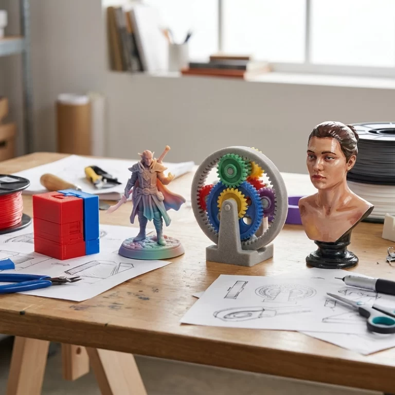
Accepted output is the number I would track. If a faster profile increases scrap, support damage, sanding time or dimensional rejects, the shop did not gain speed; it moved the cost to inspection and rework. A batch of cosmetic gifts, a batch of jigs and a batch of metal brackets can all have different bottlenecks after printing. The fastest printer setting is not always the fastest delivery route.
For process-specific limits, the articles on CLIP resin 3D printing and high-speed FDM printing are useful companion reads.
CLIP, Multi-Laser Systems and Motion Control
Continuous photopolymerization can reduce the stop-start rhythm of conventional resin printing by using a controlled oxygen inhibition layer near the optical window. It can be fast when the resin, geometry and heat behavior fit. The limit is not only exposure speed. Resin chemistry, oxygen control, heat, shrinkage stress and post-curing still decide whether the part is usable.
Multi-laser powder bed systems increase productivity in a different way. Several lasers may work in different regions of the same bed. That creates overlap-zone calibration, thermal management and quality-control challenges. Higher scan throughput can move the bottleneck to heat treatment, machining or inspection.
The source also mentioned linear motor systems with acceleration about three times higher than conventional stepper motion in some equipment, and speeds rising from around 60 mm/s to 150 mm/s under specific conditions. It also noted linear motors can cost five to ten times more than stepper systems. That is a process investment, not a simple upgrade. Frame stiffness, feedback, algorithms and material flow must all keep up.
On FDM equipment, vibration shows up as ringing near corners, rounded edges, inconsistent walls and sometimes weaker parts because the material path is being asked to keep up with a shaking motion system. Input shaping and pressure advance can help, but they do not create melt capacity. A nozzle that cannot deliver enough polymer will still under-extrude at high speed. Bigger nozzles, hotter flow, shorter layer time and stronger cooling all trade against surface detail and layer bonding.
For resin processes, speed can stress the peel step. Thin flexible layers, large cross-sections and viscous resins can create suction forces that bend the part or damage small supports. Continuous processes reduce some stop-start behavior, but they still need resin flow, heat control and post-cure. A fast green part that changes dimension during curing has not saved much time.
Cooling Limits in High-Speed Additive Manufacturing
Speed creates heat problems in both directions. In FDM, the polymer may not melt fully at high flow, causing weak layers. If it melts well but cools too slowly, corners round, overhangs sag and details smear. Too much cooling can reduce layer adhesion. In resin printing, faster cure can increase heat and shrinkage stress. In metal printing, higher laser productivity can increase residual stress and distortion.
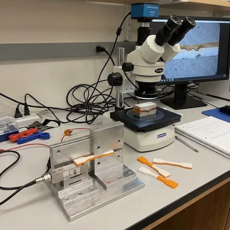
Use test parts that represent the real job: holes, thin walls, overhangs, support contact zones, visible faces and mating dimensions. Measure accuracy, surface quality, mechanical performance where relevant and repeatability across several builds. The NIST additive manufacturing resources are useful background for process thinking. The final decision is still practical: high-speed additive manufacturing is worthwhile only when it increases accepted output, not when it only makes the motion graph look faster.
For RFQ work, ask for the promised lead time as a route, not a machine claim: print time, cooling time, depowdering, support removal, curing, machining, finishing, inspection and packing. That single question often exposes where the real delay sits. High-speed additive manufacturing becomes useful when the whole route is balanced enough that speed reaches the shipping box.