3D printing surface roughness is not just a cosmetic complaint. It changes friction, sealing, paint adhesion, fluid flow, wear, cleaning, and sometimes transparency. A rough display model may still be acceptable. A rough sealing face, sliding guide, microchannel, or optical resin part can fail quietly.
I start by asking what the surface does. If it only needs to look good after paint, the answer may be sanding and primer. If it is inside a tiny channel, finishing access may be impossible and the process choice has to change.
3D printing surface roughness comes from the process path
Layer lines are the easy culprit to see. Curved and sloped surfaces become small stair steps. Thicker layers make bigger steps; thinner layers reduce them but increase time and can demand tighter process control. FDM adds extrusion width, cooling, filament moisture, and nozzle path marks. SLA adds exposure behavior, support contact, washing residue, and post-curing effects.
Powder-bed processes leave another kind of texture. SLS and MJF nylon parts often have a fine grainy surface from the powder bed. Metal SLM can be rough from partially melted particles, spatter, scan tracks, and support contact. That texture may be acceptable on a bracket, but it is usually not acceptable on a sealing face without machining or another finishing route.
Microchannels show why 3D printing surface roughness matters
Microfluidic features make the problem obvious. A channel may be only 0.1-0.5 mm wide. A size change of 0.01-0.02 mm can affect flow. Rough inner walls can trap particles, create bubbles, or change mixing behavior. A layer texture of a few micrometers may be enough to matter when the channel itself is tiny.
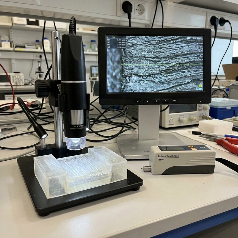
For internal channels, surface roughness and dimensional accuracy are tied together. The entrance may measure close to nominal while the inside has an irregular cross-section. That is why I do not accept a pretty outside photo as proof for fluidic or optical parts. Microscope inspection, flow testing, sectioning, or CT may be needed depending on the risk.
| Surface type | Roughness risk | Useful check |
|---|---|---|
| Visible shell | Layer lines and support marks | Raking light before paint |
| Sliding guide | Friction and debris | Fit and wear test |
| Sealing face | Leak path | Flatness, leak test, machining option |
| Microchannel | Flow change or blockage | Microscope, flow, or section check |
| Transparent resin | Haze and light scattering | Polish and clear-coat sample |
Finishing can help, but access decides the limit
Sanding works on reachable surfaces. Primer can fill small scratches before paint. Tumbling can smooth nylon batches, but it may soften sharp edges. Vapor smoothing can improve some thermoplastics, especially ABS-like materials, but too much exposure rounds features and shifts dimensions. Transparent resin needs support planning, wet sanding, polishing, and often clear coating; hidden residue can ruin clarity.
Lower layer height can reduce stair-stepping, but it is not a complete fix. For small channels, a useful starting idea is to keep layer thickness much smaller than the channel dimension, sometimes around one tenth of the channel size. That still needs validation because overexposure, powder texture, trapped resin, or support marks may dominate the final surface.
3D printing surface roughness RFQ language
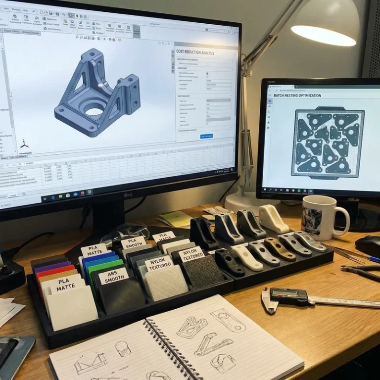
A request for “smooth surface” is too vague. I want to know whether the surface is visible, painted, sliding, sealed, optical, fluid-contact, or measured. If roughness must be specified, use a realistic measurable target and say where it applies. For many prototypes, a sample finish comparison is more practical than copying a machined-part Ra value into a printed-part RFQ.
For related choices, see 3D printing support design and SLS nylon surface finishing. For outside reading on surface measurement, NIST surface metrology resources are a useful neutral reference. My working rule is simple: decide whether the surface must look good, move well, seal, carry fluid, or transmit light before choosing the process.
On a real sample, I check surface texture under two conditions. Normal light shows the appearance the buyer will notice first. Low-angle light reveals layer steps, sanding direction, pits, and support ghosts. For functional surfaces, I do not rely on light alone. A sliding guide needs a fit test, a sealing face needs a leak or pressure check, and a fluid channel may need flow evidence.
I am careful with finish promises. A raw SLS nylon part can be dyed and tumbled, but sharp edges may soften. SLA can be sanded and painted, but support scars still need removal. Metal printed surfaces can be machined, but only where the tool can reach. 3D printing surface roughness should be discussed while the part is still in CAD, because some surfaces are easy to improve and others are locked inside the geometry.
When the surface touches another part, I ask for the mating material too. Nylon against metal, resin against rubber, and coated plastic against a gasket do not wear or seal the same way. A roughness decision that looks minor on a single printed sample can become noise, dust, friction, or leakage after assembly.