3D printed threads and inserts look small on a drawing, but they decide whether a prototype can be assembled without drama. A modeled thread may look perfect in CAD and still tear out under torque. A tapped resin hole may work once and crack the second time. A brass insert may be strong, but only if the boss around it has enough material.
I treat every thread as a load-bearing feature until the part proves otherwise. The right choice depends on screw size, assembly cycles, material, print process, load direction, and whether post-machining is allowed.
3D printed threads and inserts are three different decisions
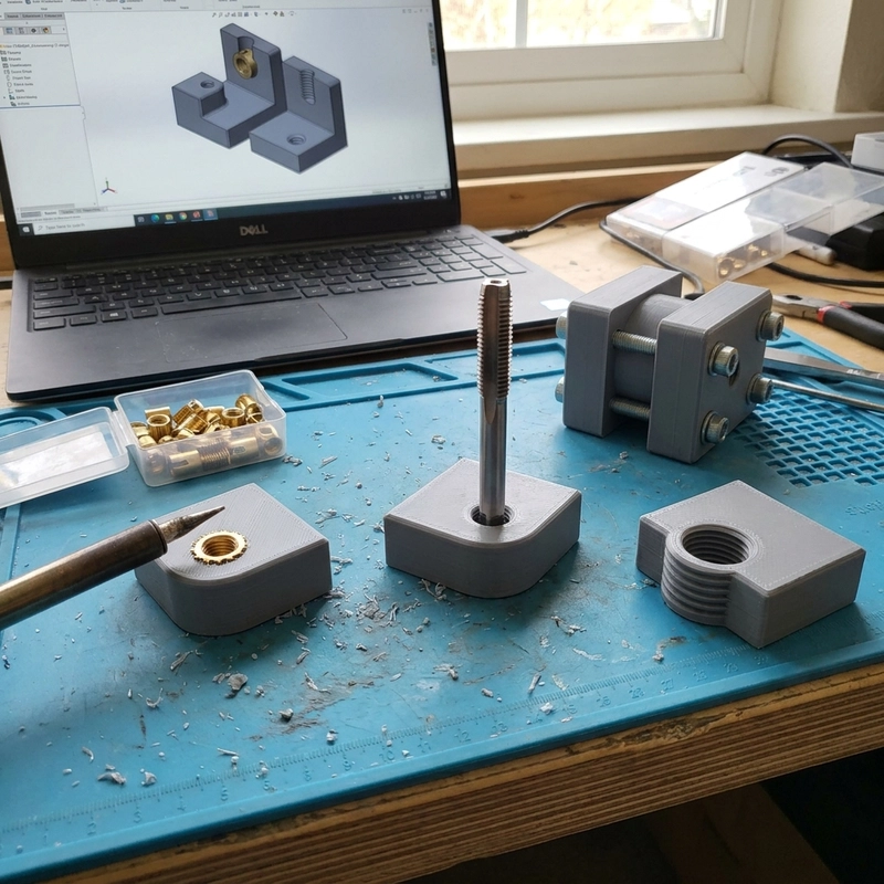
The common routes are modeled printed threads, printed pilot holes that are tapped after printing, and metal inserts. Modeled threads can work for large, low-load, or visual features. Tapped holes are often better for moderate plastic threads. Inserts are usually better for repeated assembly, higher torque, or parts that will be opened and closed many times.
The process matters. FDM holes can print slightly out of round because bead geometry defines the wall. SLA holes may come out small or brittle depending on exposure and curing. SLS and MJF nylon holes can be tough, but powder cleaning and thermal history affect size. Metal printed threads are often machined after printing when tolerance and flank quality matter.
Modeled thread geometry still needs clearance
The original source used an M10 coarse thread example. M10 coarse pitch is 1.5 mm. A standard metric thread profile uses a 60 degree form, and the theoretical height can be estimated as H = 0.866025 x P, about 1.299 mm for that pitch. Those numbers are useful because they show why a thread is not just a spiral texture on a cylinder.
For external threads, I prefer subtractive CAD logic: start with the major cylinder and remove material with the inverse tooth profile along a helix. That mirrors machining better than adding a raised spiral. For printing, the model still needs relief and practical clearance. Sharp crests, deep valleys, trapped resin, powder residue, and support scars can all make a mathematically correct thread feel wrong in the hand.
| Thread method | Useful for | Watch for |
|---|---|---|
| Modeled printed thread | Large or low-load threads | Rough flanks, weak roots, poor fit |
| Printed pilot plus tapping | Moderate plastic assembly | Cracking, wrong pilot size, stripping |
| Heat-set insert | FDM thermoplastic with repeat screws | Overheating, misalignment, thin boss wall |
| Bonded or press insert | Resin or nylon when heat is risky | Loose fit, adhesive creep, splitting |
| Post-machined thread | Metal or precision plastic parts | Machining allowance and setup cost |
Boss design matters more than the thread note
A strong screw joint needs material around it. Thin posts split at the root. Holes too close to an edge break under tightening. Sharp boss bases concentrate stress. I usually add fillets, increase boss diameter, move holes away from edges, and use washers or load-spreading geometry when the screw does more than hold a cover in place.
Heat-set inserts are common in FDM parts because the plastic can flow around the knurled insert. The insertion temperature should be controlled so the insert seats straight without sinking too far. SLA resin is more fragile under heat, so bonded or press-fit inserts may be safer, but they still need testing. Nylon powder parts can take inserts well when the hole is cleaned and the boss is thick enough.
3D printed threads and inserts need a torque reality check
Before printing, I ask for screw size, pitch, expected assembly cycles, torque if known, pull-out load, wall thickness, material, tool access, and whether the thread can be drilled, tapped, or machined after printing. For functional parts, a drawing note is better than hoping the STL communicates thread intent. For strength context, see 3D printed part strength; for hybrid finishing, see CNC machining after 3D printing.
For metric thread terminology, I cross-check against standards such as ISO metric screw thread documentation, then design for the print process instead of blindly copying nominal geometry. My rule is simple: if the screw will be used more than once or carries load, do not leave the thread method as a last-minute detail.
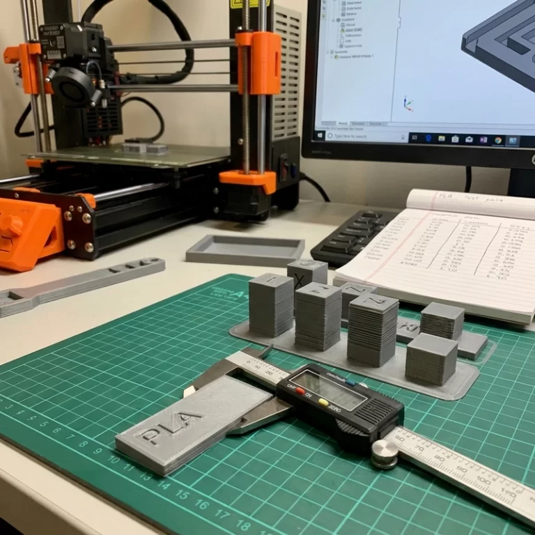
One small test saves a lot of guessing: print a boss strip with the actual pilot hole, wall thickness, insert type, and material. Tap it, install the insert, tighten the screw, then remove and reinstall it a few times. The result is not a certified torque test, but it quickly shows whether the feature is brittle, undersized, loose, or too close to an edge.
For production notes, I also mark which threads are functional and which are only for positioning. A cosmetic cover screw may tolerate a printed or tapped plastic thread. A clamp, hinge, fixture, or vibration-loaded part usually should not. Good 3D printed threads and inserts are not only about making the screw start; they are about making the assembly survive the way the user will actually tighten and handle it.
If the part is going to painting or dyeing, I check the thread after finishing too. Coating can tighten a printed thread, sanding dust can sit in a tapped hole, and resin residue can harden in a blind feature. 3D printed threads and inserts should be approved in the same finished condition the buyer will receive, not in a cleaned-but-unfinished sample.