
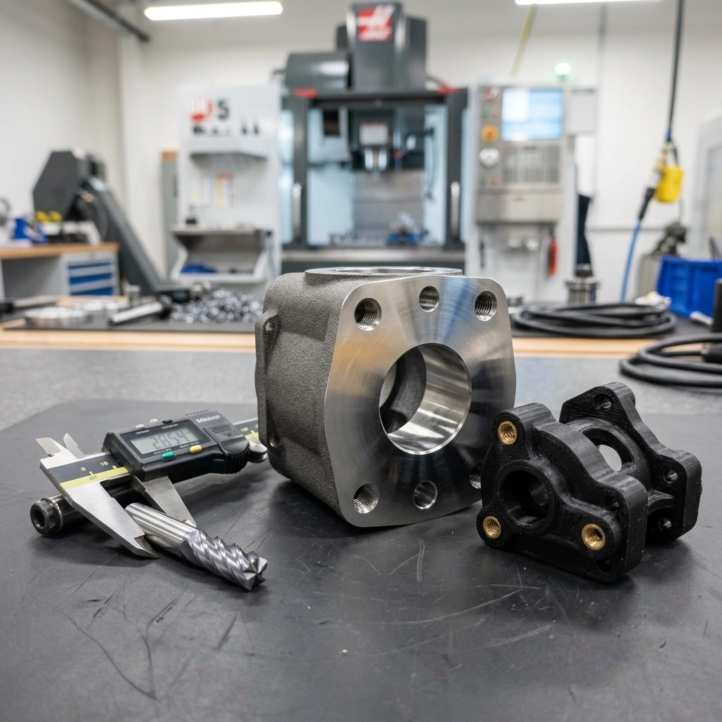
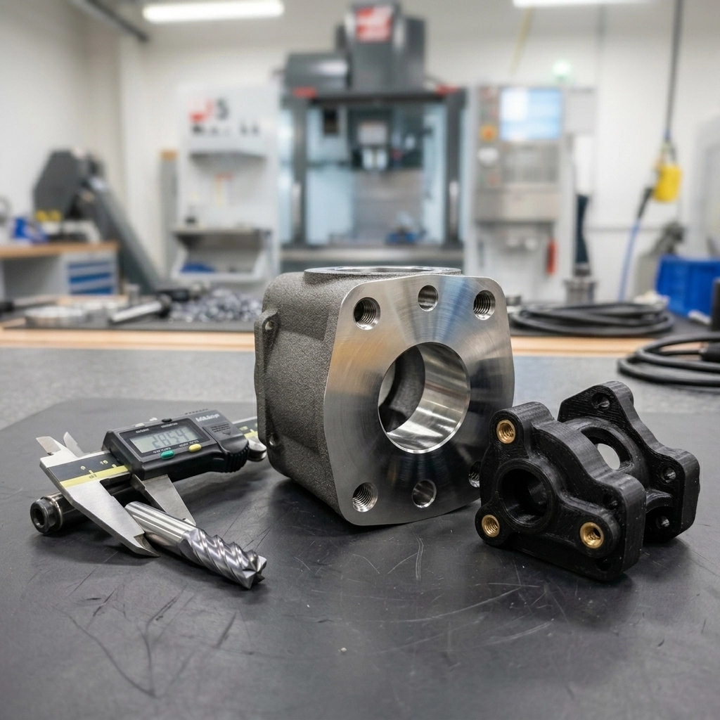
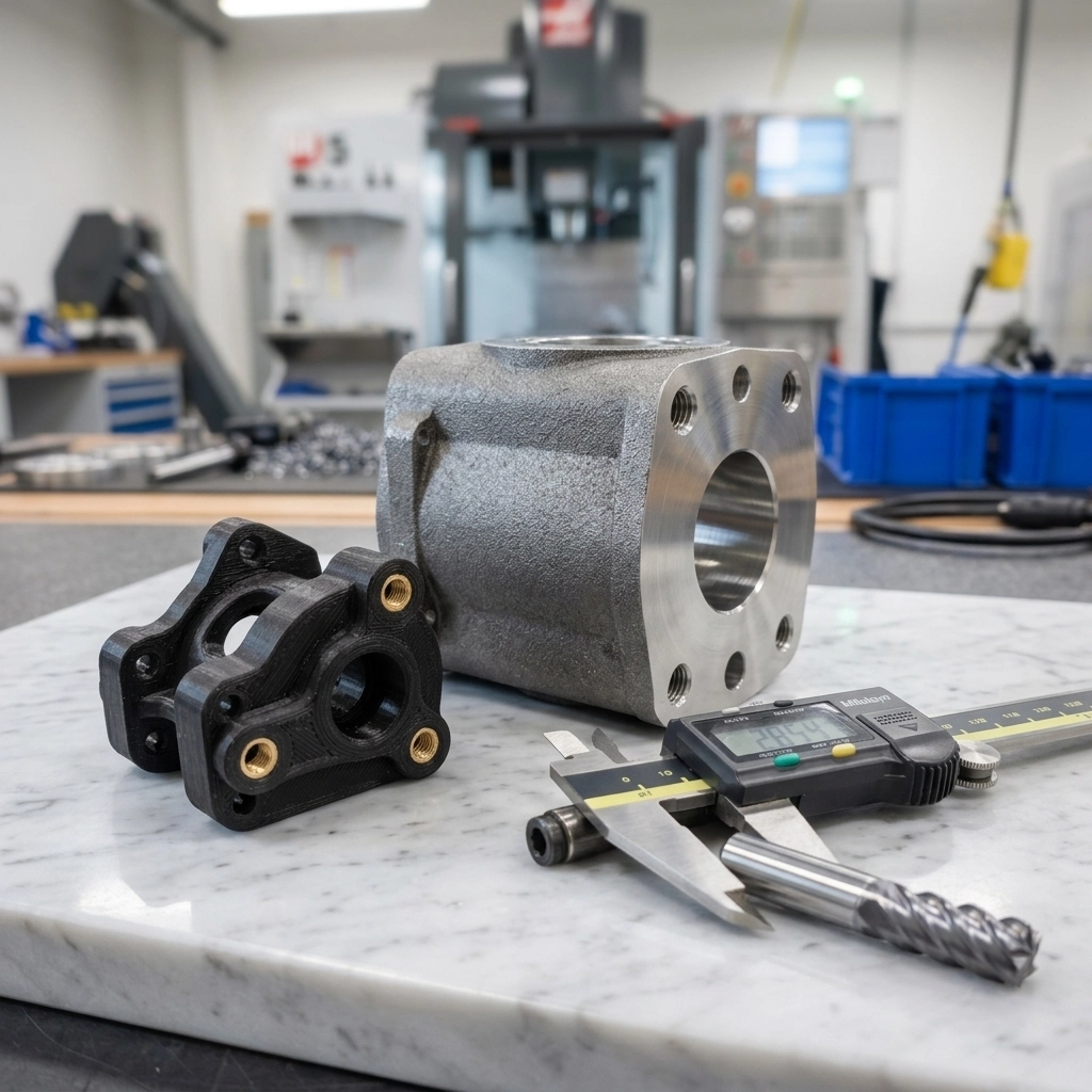
CNC Machining and 3D Printing Hybrid Service
Combine additive geometry with CNC-machined datums, bores, threads and sealing faces. Send STEP files and drawings for review of machining allowance, fixture access, process sequence, tolerance and inspection.
Description
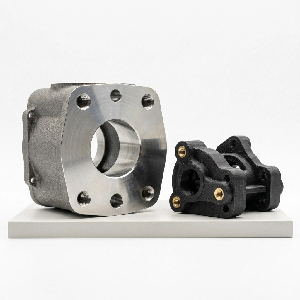
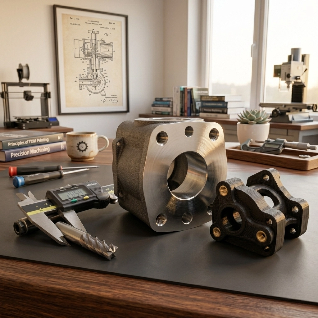
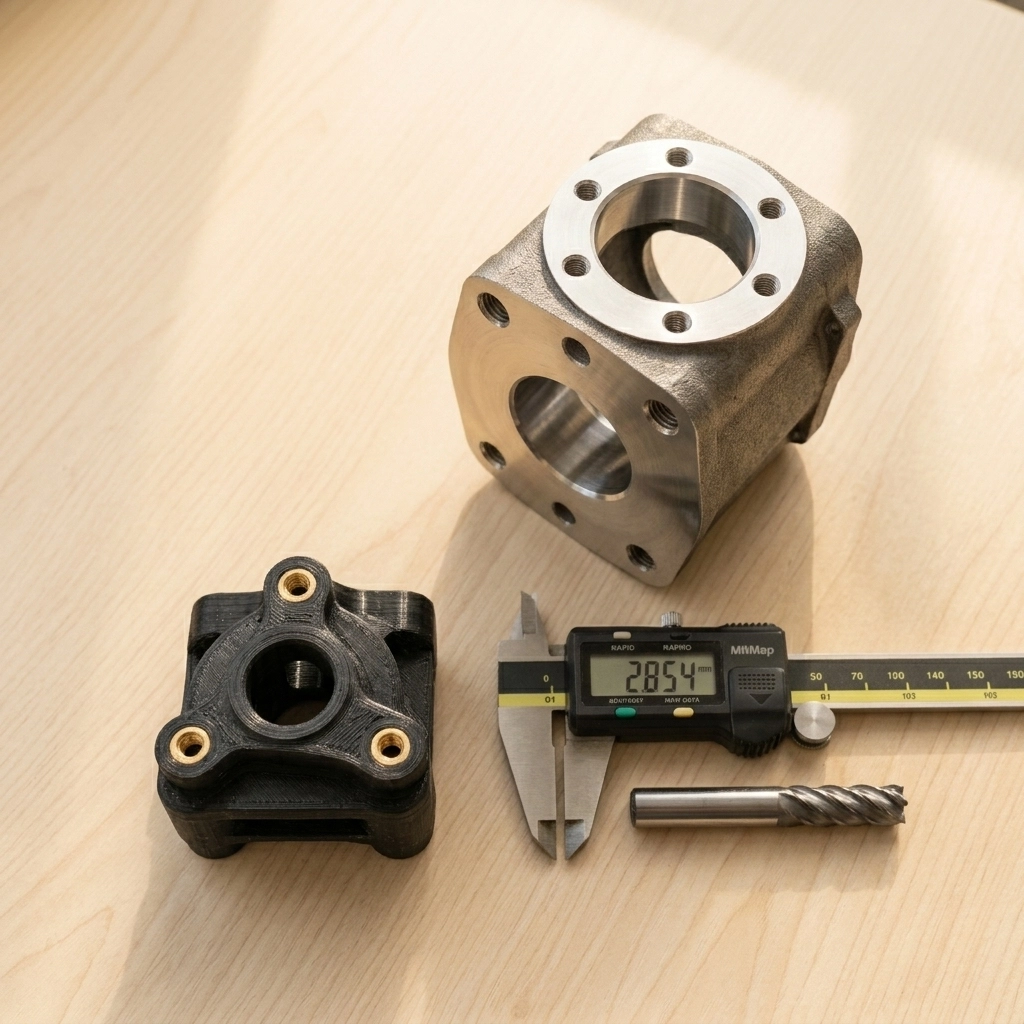
CNC and 3D printing hybrid service is useful when the printed process creates the shape and machining creates the interfaces. A manifold may need printed internal channels but machined ports. A nylon housing may be acceptable as-built except for locating holes. A resin master may need one flat reference face before it can enter another process.
The mistake is treating CNC as a repair step after printing. By then the part may have no stable datum, too little stock, poor tool access or a surface that cannot be clamped without damage. Hybrid manufacturing works better when the printed preform and the machining setup are designed together.
A CNC and 3D Printing Hybrid Service Needs Two Definitions of Finished
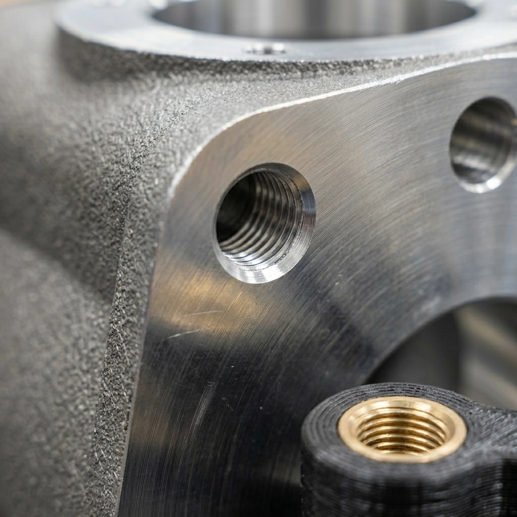
The first definition is the printable preform: build orientation, supports, wall transitions, escape holes and enough material around areas that will be cut. The second is the accepted component: finished datums, bore sizes, threads, surface roughness, coating condition and inspection requirements.
Those two models do not always have identical geometry. A bore may be printed small and opened later. A sealing face may carry sacrificial stock. Temporary tabs can provide a grip for machining and then be removed. If only the final CAD model is supplied, these manufacturing features still have to be planned somewhere.
I prefer a STEP model plus a drawing that marks the features that actually control function. Applying a tight tolerance to every surface usually adds confusion and cost without improving the assembly.
Datum Transfer Is the Quiet Difficulty
A machined block arrives with surfaces that can often be located directly. A printed body may be curved, textured or slightly distorted. The machining setup needs to connect that imperfect preform to the drawing datums. NIST has described the challenge of tolerance transfer in additive manufacturing: design intent may use several datum reference frames even though the layer-based build begins from a common process reference.
This becomes practical at the fixture. Which surface touches first? What prevents rotation? Can the clamp force deform a thin nylon shell or crack a brittle resin edge? Is there enough repeatable geometry to locate a second part the same way? Sometimes the answer is a printed sacrificial pad or boss. Sometimes it is a soft jaw, potting fixture or custom nest. The right choice depends on material, quantity and the features being machined.
Machining Allowance Is Not One Universal Number
Stock has to cover expected print deviation, surface texture and setup uncertainty. Too little stock risks an interrupted cleanup where part of the surface remains untouched. Too much stock adds printing time, cutting load and local mass that may change thermal behavior. Allowance should be assigned by feature, process and orientation, not copied across the entire model.
A metal printed sealing face, an SLS nylon bearing pocket and an FDM fixture base do not need the same strategy. The machining method matters too. A reamed hole, faced pad and multi-axis contour each use stock differently. When the tolerance is demanding, the inspection plan and setup sequence should be agreed before allowance is frozen.
Tool Access Can Cancel a Good-Looking Hybrid Design
Additive manufacturing can place a precision feature deep behind a wall or beside a curved obstruction. CNC still needs a cutter, holder, spindle approach and chip-clearance path. A hole may be visible in CAD but unreachable with a rigid tool. A thread beside a tall rib may require a longer tool that deflects. Internal channels that make printing attractive can also limit how a machined port intersects the passage.
Check access from the tool axis, not from the camera angle. Five-axis machining expands the available directions but does not remove holder collision, workholding or minimum tool size. If the interface cannot be reached, moving the feature, adding a removable section or machining before an assembly operation may be cleaner than forcing the toolpath.
The Print Material Changes the Cutting Plan
Metal preforms
Residual stress, heat treatment and plate removal can change the shape before cutting begins. Datums may need to be established after stress relief, and critical faces need enough stock to clean up after distortion. The SLM metal 3D printing service page explains why the build-to-CNC sequence must be agreed early.
Nylon and engineering plastics
Thin polymer walls can move under clamps, heat and cutting force. A rigid fixture may hold the part in a distorted state and release it after machining. Sharp tools, controlled support and realistic tolerances matter more than trying to make the setup behave like a solid aluminum block.
Photopolymer resin
Resin parts may be brittle or sensitive to localized stress. Machining can help create a reference face or selected hole, but fragile edges and thin features need support. If the part is only a visual model, sanding or a revised print orientation may be more sensible than CNC.
Use CNC Only Where It Buys Function
Good hybrid candidates usually have a small set of demanding features surrounded by geometry that printing handles well. Common examples are bearing seats, O-ring lands, flat mounting pads, dowel holes, threaded ports and datum faces. Machining every accessible surface can erase the cost and geometry advantage that justified printing.
The reverse is also true. If most of a part is prismatic and every important face needs cutting, start from stock and machine it conventionally. A CNC and 3D printing hybrid service should reduce process difficulty, not add an additive step to an ordinary machined component.
Inspection Follows the Final Datum Scheme
Inspection for a CNC and 3D printing hybrid service order should distinguish as-printed geometry from machined acceptance features. A CMM may reference finished datums, while a scan compares freeform printed surfaces. Thread gauges, pin gauges, surface roughness measurement or leak testing may be appropriate for specific interfaces. The drawing should state what is accepted after all finishing, not leave the inspector to compare an intermediate preform with final CAD.
NIST’s paper on tolerance transfer for additive manufacturing provides useful context for datum references and post-processing. It does not set a universal tolerance; those values remain part-specific.
CNC and 3D Printing Hybrid Service RFQ Checklist
- STEP model of the finished part and, when available, the intended printed preform;
- drawing with datums, critical dimensions, fits and surface requirements;
- printing process, material and post-print material condition;
- features requiring machining and surfaces that may remain as-printed;
- quantity, fixture repeatability and first-article approval needs;
- coating, assembly and inspection sequence after machining.
The 3D printing file preparation guide helps separate mesh files, STEP geometry and drawing notes. If the part should be machined directly from stock rather than printed first, use the standalone CNC machining service. Return to the custom 3D printing service hub if the production route is still open. For a manual CNC and 3D printing hybrid service review, send the model, drawing and quantity through the RFQ contact page.