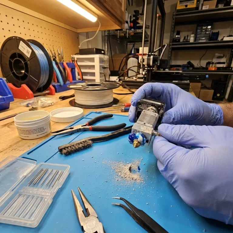
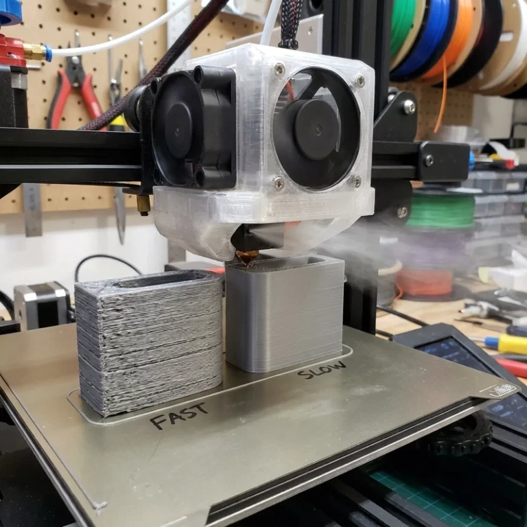
PEEK 3D printing depends on the exact grade, equipment and thermal history. Warping, interlayer bonding, crystallinity and final dimensions need to be evaluated together. The controls below are a process-review framework, not a universal temperature recipe or evidence that a particular supplier’s PEEK route is qualified.
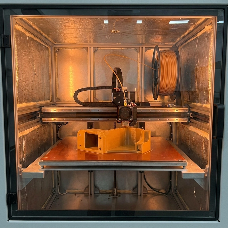
What PEEK Actually Needs (Most Machines Can’t Deliver)
Select a printer and material combination with a supported PEEK profile. Review extrusion, build-surface and chamber control together with drying, support and cooling requirements. Maximum advertised temperatures alone do not prove that the system can hold the required conditions through the planned build.
Confirm the complete process with the equipment and material suppliers rather than treating “PEEK-capable” as a property guarantee. The final part still needs inspection and application-relevant testing.
Nozzle Temperature: Use the Exact Material Profile
Use the extrusion range specified for the selected PEEK grade and supported printer profile. Check temperature sensing, flow and hardware limits. Excess heat or residence time can degrade a polymer; a shared nozzle setpoint is not appropriate for every neat or filled PEEK formulation.
Before a long build, verify temperature-control stability and machine readiness under the equipment’s approved procedure. Do not use an arbitrary sustained-temperature test or operate the hot end outside its rating.
Chamber Control: The Difference Between a Print and a Part
Chamber control affects the thermal history of deposited material and the conditions experienced by successive layers. Review the intended crystallization and cooling strategy with the supported profile rather than simply maximizing chamber heat.
Uneven cooling through a tall part can contribute to stress and distortion. Record actual process conditions and inspect the fully cooled part. Nozzle temperature is not the temperature of the entire upper section of a print.
For accuracy-critical work, agree on the supported chamber and cooling strategy and verify the final dimensions after any required thermal treatment.
Material Drying: Follow the Grade-Specific Instructions
Check the filament supplier’s drying, storage and handling instructions for the exact grade. Use equipment rated for the required conditions and maintain a suitable path to the printer. Moisture symptoms do not establish a universal drying temperature or duration.
Ask for the drying record and subsequent storage conditions. A dry-storage box and an active drying process are not necessarily equivalent; confirm the permitted method rather than assuming the material is ready from its packaging history.
Crystallinity and Annealing: The Post-Process Most People Skip
PEEK is semi-crystalline, and its thermal history can affect crystallinity, dimensions and properties. A process may intentionally control the as-printed condition and use a subsequent treatment. Evaluate the grade and qualified route; do not infer heat resistance or toughness solely from color, a cool-down rate or a generic annealing label.
| Control point | Why it matters | Risk if uncontrolled |
|---|---|---|
| Nozzle temperature | Melts PEEK fully for extrusion | Under-extrusion or degradation |
| Chamber temperature | Controls cooling and layer bonding | Warping, cracking, delamination |
| Material drying | Reduces bubbles and weak layers | Rough surface, lower strength |
| Annealing | Controls the specified final material condition | Dimensional change if not planned |
| Design orientation | Aligns strength with load path | Layer splitting under service load |
Use an annealing cycle only when specified for the grade, geometry and intended material condition. Plan fixturing, cooling and post-treatment inspection. Do not apply a shared shrinkage percentage to compensate CAD; measure representative parts under the actual process before changing critical dimensions.
Design Limits: FDM Physics Still Apply
PEEK does not remove the directional and geometric effects of FFF. Review the load path, interlayer behavior, wall transitions and support locations. Use relevant material data and representative testing to select orientation rather than assuming a universal weakest direction or strength penalty.
Mark critical holes, threads and sealing faces on the drawing. Review whether the printed route can meet their requirements or whether machining, inserts or another design is needed. Printed features are not automatically acceptable or automatically unusable without defined tolerances and testing.
When PEEK Isn’t the Answer
Compare PEEK with other materials against the actual temperature, chemical exposure, loads and inspection requirements. A less costly material may be suitable for a geometry check, but price multiples and one temperature threshold cannot establish equivalence among PEEK, PC, PEI, nylon and resin.
Choose PEEK when the specified material condition and validated process address a real application requirement. Otherwise compare suitable alternatives using the same acceptance criteria.
RFQ Checklist for PEEK Parts
- Service temperature: state continuous and peak conditions, duration and loading, then check data for the exact grade and final material condition.
- Chemical exposure: what fluids, what concentration, what duration. PEEK is excellent here, but confirm compatibility.
- Load direction and magnitude: this decides orientation and wall thickness.
- Annealing: required or not? If yes, which dimensions are critical after annealing?
- Machining allowance: identify holes, threads and sealing surfaces, then agree stock with the processor based on access, distortion risk and tolerances.
- Inspection: which features must be measured after final thermal cycle?
Keep the selected grade, machine profile, thermal treatment and inspection requirements together in the RFQ. For manufacturer context, see INTAMSYS’ PEEK process overview. It describes a coordinated equipment–material workflow; it is not a Zesmir equipment claim or a substitute for project-specific qualification.