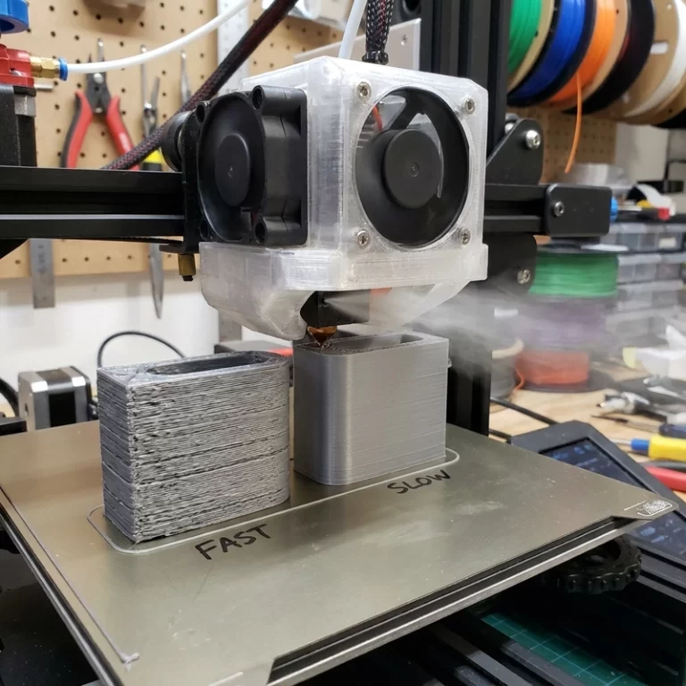
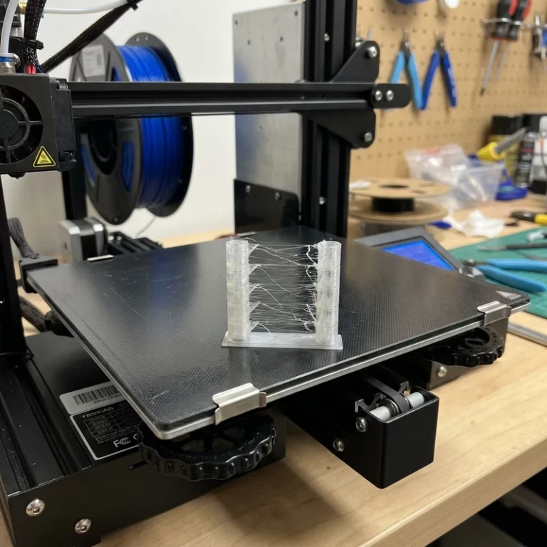
FDM layer adhesion controls whether a functional prototype survives load, vibration or repeated assembly. A material datasheet usually describes a standardized specimen, while a printed part adds orientation, bead geometry, cooling and moisture effects. When a part splits along layer lines, diagnose the thermal and material history before assuming the polymer itself is unsuitable.
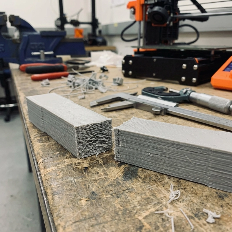
FDM is anisotropic because continuous roads and interlayer bonds carry load differently. Published percentages for Z-direction strength vary widely with material, specimen, orientation and test method, so they should not be treated as universal design factors. For critical parts, test a representative coupon or first article made with the planned process settings.
Nozzle Temperature: The Dominant Variable in FDM Layer Adhesion
Nozzle temperature strongly affects interlayer diffusion, but hotter is not always stronger. Raise temperature only within the published material range and watch for discoloration, bubbling, sagging or degradation. A controlled temperature ladder on representative coupons is more defensible than quoting a single strength gain from an unverified shop test.
The workable temperature window varies by material, machine and grade. PLA, ABS, nylon and PC require different nozzle, cooling and chamber conditions. Use the published starting range for the filament, verify sensor calibration and adjust with coupons. High-temperature materials also need control of the surrounding thermal environment; nozzle temperature alone cannot compensate for layers that cool too quickly.
Cooling Fan and Chamber Temperature Balance
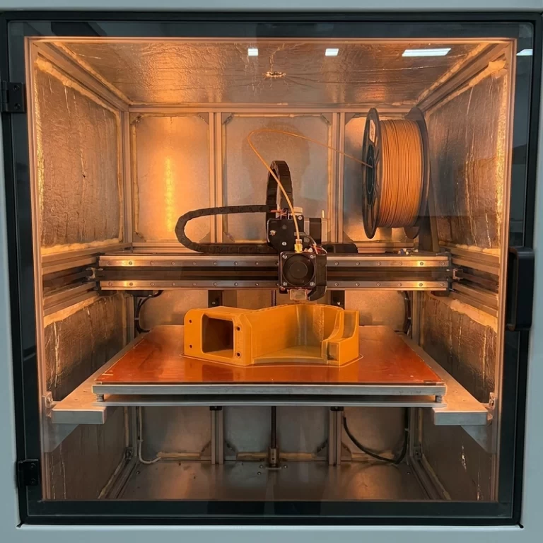
Cooling is the second-most-common cause of poor layer adhesion I encounter. PLA tolerates—and for fine detail, benefits from—100% cooling fan after the first few layers. PETG works best at 30–50% fan, enough to prevent sagging on overhangs but still allowing interlayer fusion. ABS, ASA, nylon and PC should be printed with the part cooling fan off or below 20%, and the printer must be enclosed with the chamber heated to at least 45–50 °C for ABS/ASA and 60–80 °C for PC and nylon. Without an enclosure, the part cools unevenly—the bottom layers contract while the top layers are still hot, creating tensile stress at the interlayer boundary that manifests as delamination either during printing or under load later.
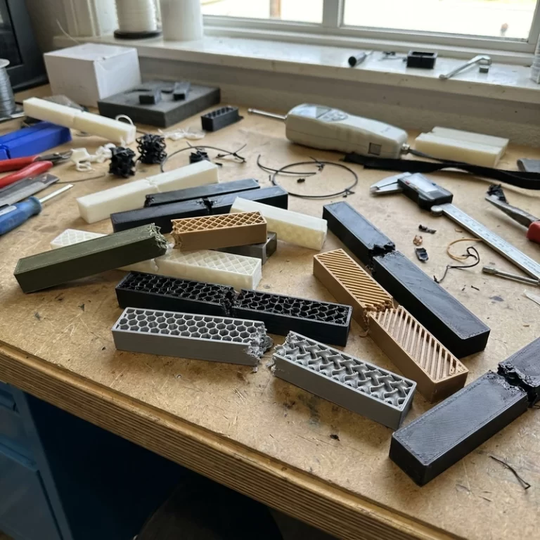
A simple screening coupon can reveal weak interlayer bonding before a full part is printed. Use a documented geometry, material condition and print recipe, then inspect whether failure follows a clean layer interface or shows more ductile tearing. Hand flexing is only a qualitative screen; quantified acceptance requires a defined test method and specimen.
| Material | Nozzle Range (°C) | Bed (°C) | Fan (%) | Enclosure | Z-Strength (% of XY) |
|---|---|---|---|---|---|
| PLA | 195–220 | 50–60 | 100 | Optional | 60–75% |
| PETG | 230–255 | 70–85 | 30–50 | Optional | 65–80% |
| ABS/ASA | 240–260 | 100–110 | 0–20 | Required (≥45 °C) | 55–75% |
| PA6 (Nylon) | 260–280 | 80–100 | 0 | Required (≥60 °C) | 50–70% |
| PC | 280–310 | 110–130 | 0 | Required (≥70 °C) | 50–65% |
| TPU (95A) | 220–240 | 40–60 | 0–20 | Optional | 80–95% |
Print Speed and Layer Height: Heat Transfer and Stress Concentration
Print speed changes the time available for heat transfer between layers. Slower outer walls may improve bonding for some engineering materials, but the optimum depends on nozzle size, layer height, temperature and geometry. Establish the production speed with controlled coupons or a representative first article instead of applying one shop-wide number.
Layer height affects adhesion through the thermal mass of each bead. Thick layers (0.28–0.32 mm on a 0.4 mm nozzle) contain more thermal energy and can re-melt the previous surface more effectively—but they also create deeper layer-line notches that act as stress concentrators. Thin layers (0.12–0.16 mm) produce smoother surfaces and more consistent fusion but transfer less heat. My default for functional parts is 0.20 mm on a 0.4 mm nozzle: a balanced point where the thermal mass is sufficient for good bonding and the surface quality is adequate for most non-cosmetic applications. For optically-inspected or fluid-sealing parts, I drop to 0.12 mm and accept the longer print time.
Material Dryness as an Adhesion Variable
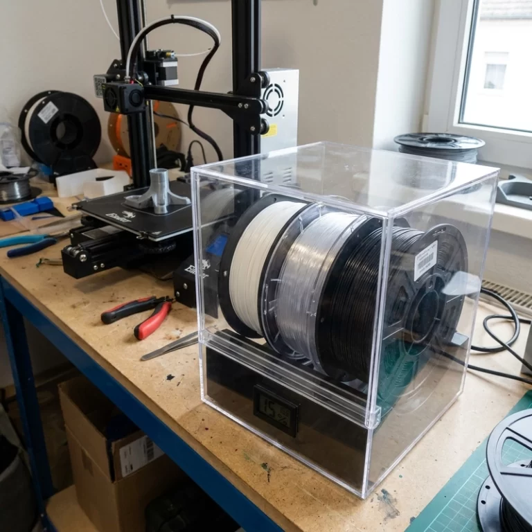
Moisture can create steam bubbles and interfacial voids that reduce bonding. Dry nylon, PC, TPU and other hygroscopic grades according to the published condition, keep them dry during long builds and document the process. Numeric strength or moisture claims should come from a defined test method and traceable sample, not an anecdotal spool comparison.
Orientation and Design: Where Engineering Overrides Printing
Because FDM parts are anisotropic, orientation should follow the load path. Identify whether the feature is loaded in tension, bending, flexure or pull-out, then place continuous roads where they can carry the primary load. If the load direction is uncertain or multidirectional, compare orientations or select a more isotropic process.
When orientation alone cannot solve the problem—for example, a screw boss that must be printed vertically for dimensional accuracy but sees pull-out force perpendicular to layers—I add design reinforcement. Heat-set threaded inserts distribute pull-out force across multiple layers; filleted ribs at screw boss bases reduce the stress concentration at the boss-to-wall transition; increasing wall count from 2 to 4 or 5 provides more fused material in the load path. Infill percentage is oversold as a strength fixer: a part with 4 perimeters and 20% infill often outperforms a 2-perimeter part at 80% infill because the perimeters carry the bending stress and inter-perimeter bonding is better than perimeter-to-infill bonding.
Validation: Test What Matters, Not Just a Coupon
Tensile coupons printed flat tell you XY-direction strength, which is not the number you need for a part loaded in Z. I validate layer adhesion on a feature-representative geometry: for screw bosses, I print a boss in the production orientation and do a pull-out test with a bolt and a spring scale; for clips, I print the clip feature and cycle it 10 times by hand; for sealing surfaces, I submerge the part in water and check for leaks at the layer lines. These tests take 30–60 minutes and catch orientation-related adhesion failures before the production build runs.
For structural FDM work, record the material and lot, drying condition, nozzle and bed temperatures, chamber condition, cooling, speeds, layer height, wall count, infill and orientation. A strong sample is not repeatable without its process history, and that record is essential when a later batch must match the approved first article.
Troubleshooting Sequence for Poor FDM Layer Adhesion
- Dry the filament and verify smooth extrusion with an extrusion test.
- Increase nozzle temperature in 5 °C increments within the material’s published range; test a small tower after each step.
- Reduce or disable the part cooling fan for ABS, ASA, nylon, PC and TPU.
- Verify enclosure temperature: minimum 45 °C for ABS/ASA, 60 °C for nylon, 70 °C for PC.
- Slow outer wall speed to 25–35 mm/s to increase heat transfer dwell time.
- Re-orient the part so the primary load direction aligns with continuous filament paths.
- Add perimeters, fillets, ribs or threaded inserts where stress concentrates at layer boundaries.
Strong FDM parts require material, design and process to work together. Material choice sets the possible performance range; interlayer bonding determines how much of that range the printed orientation can use. Validate a first article against the project requirement before releasing a batch.
Need FDM parts where FDM layer adhesion is critical to function? Contact Zesmir with your load case and acceptance criteria—we will quote the right material, print orientation and process validation for your application.