Multi-material 3D printing interface bonding usually fails in the place the render hides: the boundary between two materials. A rigid shell can print cleanly, a flexible gasket can print cleanly, and the finished part can still peel apart where the two meet. I do not treat multi-material work as a color swap. I treat the interface as its own part.
The boundary has to manage temperature, surface energy, shrinkage, stiffness mismatch, timing and geometry. If those factors are ignored, the part may look continuous and still fail under bending, peel, shear, heat or repeated assembly. Multi-material 3D printing interface bonding needs design features and test coupons, not just compatible-looking material names.
Multi-Material 3D Printing Interface Bonding Has Three Routes
Most interfaces rely on mechanical interlock, diffusion bonding, chemical bonding or a mix of all three. Mechanical interlock is often the most practical: serrations, holes, ribs, dovetails or textured surfaces allow one material to lock into the other. The source mentioned a 0.2 mm deep serrated interface improving PLA and TPU bonding by about 40% when placement error stayed below 0.05 mm. That number is process-specific, but the lesson is useful: geometry can help when chemistry is weak.
Diffusion bonding needs both materials warm enough for polymer chains to move across the boundary. The source described compatible ABS/PC interfaces with a 5-10 micrometer diffusion zone reaching roughly 80% of a single-material reference in controlled conditions. Chemical bonding is more specialized. Plasma treatment, coupling agents or reactive coatings can help, but only when surface preparation, humidity and temperature are controlled.
Timing is easy to overlook. If the second material arrives after the first surface has cooled or skinned over, the bond becomes mostly mechanical even if the two polymers look compatible on paper. If the second material arrives too hot, it can distort the first feature or smear a sealing edge. Multi-nozzle purging, tool-change delay and wipe-tower behavior can all show up at the interface, not only in the waste block.
Compatibility Is a Window, Not a Yes-or-No Answer
A direct thermal bond usually works better when the melting or softening temperature gap is not too large. The source gives about 50 C as a practical starting limit. PLA may process around 175-210 C depending on grade and settings, ABS closer to 220-240 C, while PEEK is far higher. Trying to join everything directly in one thermal pass can distort the lower-temperature material or freeze the higher-temperature interface too quickly.
Thermal expansion mismatch matters after the print cools. Surface energy controls wetting. The source notes that a surface tension difference below about 10 mN/m and contact angle below 30 degrees can help wetting. PLA around 40 mN/m and TPU around 35 mN/m explains why that rigid-flex pair can be workable when timing and temperature are managed. These values should be treated as screening data, not final proof.
Stiffness mismatch can be worse than poor wetting. A soft TPU lip bonded to a rigid PLA shell may peel because the soft side bends while the rigid side does not. A thin rigid rib inside a flexible body can cut into the interface during repeated flexing. I look for rounded transitions, wider overlap and load paths that put the interface in compression or shear rather than peel whenever the geometry allows it.
For material selection around rigid and flexible plastics, link this back to engineering plastic 3D printing material selection. If the interface becomes a moving hinge, 3D printed moving joints is the more practical next check.
Testing Multi-Material 3D Printing Interface Bonding
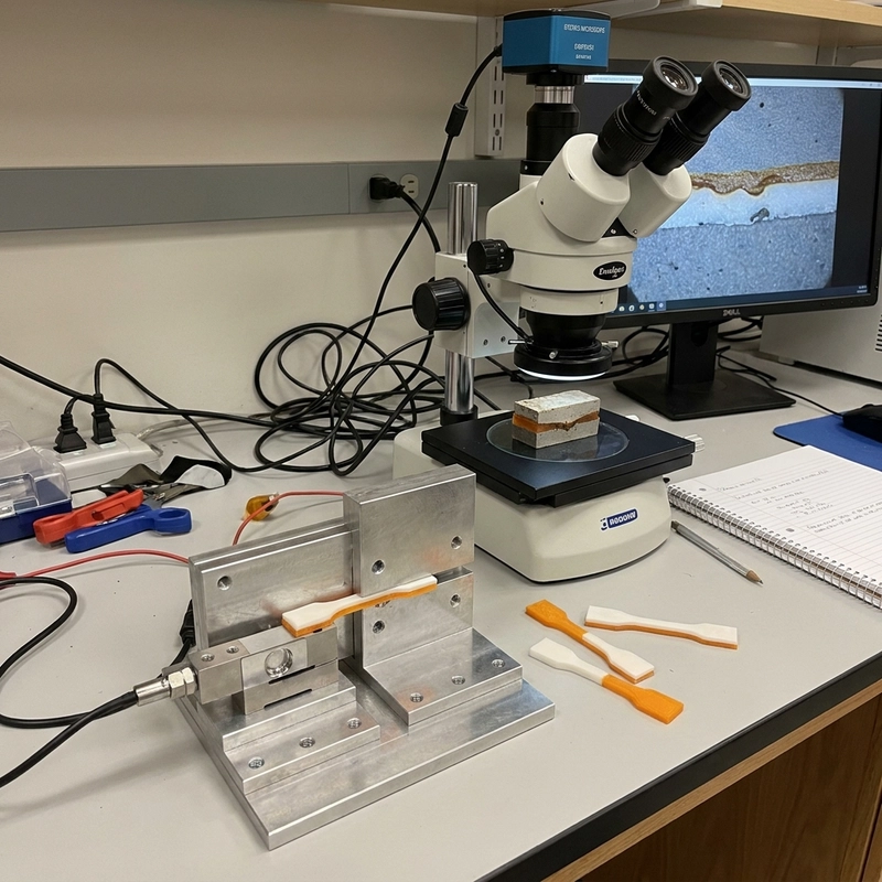
Visual inspection is weak evidence. A part can look bonded and still peel at the edge. The source described lap shear specimens around 10 x 20 x 3 mm with a 5 mm overlap and pull speed around 5 mm/min. Flexible interfaces may need 90-degree peel testing at about 30 mm/min. A structural requirement should define its own target; do not borrow a random MPa value from another material pair.
Gradient transitions can help by spreading stress across several layers instead of making a hard boundary. A five-layer PLA-to-TPU transition reached around 70% of single-material shear strength in one source example, while direct boundaries were lower. Mechanical anchors around 0.5 mm placed every five layers improved peel resistance in another example. These details are not universal recipes. They show why interface geometry should be designed and tested.
Failure inspection should be part of the test, not only the final force number. If the flexible material tears while the interface stays intact, the bond may be stronger than the soft material. If the interface peels cleanly with shiny surfaces, wetting or temperature may be weak. If one side carries crumbs from the other, mechanical interlock helped. Those fracture surfaces tell you whether to change material, temperature, overlap or geometry.
The ISO/ASTM 52900 additive manufacturing vocabulary is useful for keeping process language clear, but it does not validate a specific bond. For RFQ work, send both materials, load direction, bend radius, operating temperature, chemical exposure, required peel or shear behavior, cosmetic limits and whether the interface must seal, conduct, flex or only locate. Multi-material 3D printing interface bonding is where the part earns trust, or quietly loses it.