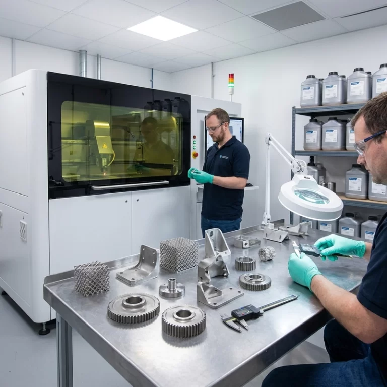
Metal 3D printing post-processing is where a printed metal part either becomes usable or quietly turns into an expensive rough blank. I do not treat it as the cleanup step after printing. Support removal, stress relief, HIP, CNC machining, blasting, polishing, coating, and inspection all change the part in different ways. Get the order wrong and the part can move, crack, lose datum surfaces, or pass visual inspection while hiding porosity inside.

The part file does not tell the whole story. A titanium bracket, a stainless steel fixture, a conformal cooling insert, and a visual metal sample may all come out of a powder-bed machine, but they should not go through the same finishing route. When I review metal 3D printing post-processing, I want to know what surfaces are functional, where the supports touch, which features will be machined, whether fatigue matters, and when inspection will happen. Those decisions should be made before the build, not after the operator is holding a part full of supports.
Choose the Post-Processing Route Before the Build Starts
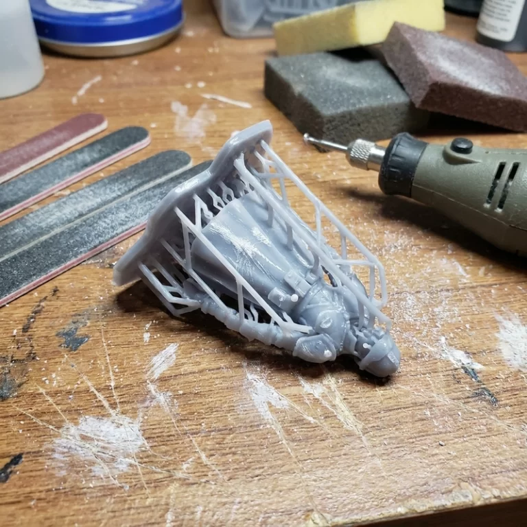
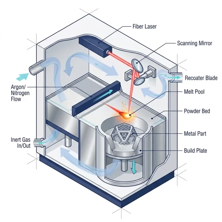
Metal supports are not like resin supports that snap away with a little cleanup. In SLM and related laser powder-bed processes, supports anchor the part, conduct heat, and fight distortion during the build. They may need wire EDM, a band saw, grinding, or machining. A thin wall or lattice can survive printing and still get damaged during support removal if the removal force was not considered in the design.
The build plate separation step is where I get cautious. If the part holds a lot of residual stress and gets cut from the plate too early, it may move as the stress releases. Sometimes the shift is obvious. Sometimes it is just enough to ruin a sealing face or move a hole pattern. This is why metal 3D printing post-processing cannot be planned only from the final surface finish. The sequence matters.
Stress Relief Is Not Optional for Every Job, But It Is Not Magic Either
Laser powder bed fusion creates steep thermal gradients. Stress relief reduces locked-in stress before heavy support removal, plate separation, machining, or service loading. In the source notes for this article, Ti6Al4V stress relief was listed around 650 degrees C for 2 hours, while one 316L stainless steel workflow used around 450 degrees C for 1 hour. I would not copy those cycles blindly into a purchase order. The alloy grade, powder route, customer specification, and required properties decide the real cycle.
Stress relief does one job well: it reduces residual stress. It does not heal a bad print. Lack-of-fusion voids, severe cracks, trapped powder, unsupported thin features, and poor geometry remain problems. If a part was printed outside a sensible process window, heat treatment may make it less stressed, but it will not turn it into a qualified component. For defect background, I would pair metal 3D printing post-processing with SLM metal 3D printing defects before deciding what a post-process can realistically fix.
| Step | What it is trying to fix | What I would not assume |
|---|---|---|
| Stress relief | Residual stress before cutting, support removal, or machining | It does not close lack-of-fusion voids or erase cracks |
| HIP | Internal pores and microcracks in critical parts | It is not needed for every visual sample or light fixture |
| CNC machining | Datum faces, holes, threads, bearing seats, sealing surfaces | Raw printed surfaces rarely replace machined critical faces |
| Blasting or tumbling | Loose powder, texture, support witness marks, edge feel | It does not create tight tolerance or remove deep defects |
| Inspection | Dimension, density, surface roughness, internal quality | One visual check is not a quality plan |
HIP in Metal 3D Printing Post-Processing: Use It for the Right Reason
Hot isostatic pressing uses high temperature and high pressure to close certain internal pores and microcracks. For critical Ti6Al4V work, the source workflow referenced about 920 degrees C, 100 MPa, and 2 hours, with density reported near 99.8% after a controlled process. Those numbers are useful as context, not as a universal recipe. HIP depends on alloy, build quality, part geometry, and the property target.
I do not specify HIP just because a part is metal printed. For a display sample, a low-load fixture, or a part where surface appearance matters more than fatigue, HIP may add cost without much practical value. For fatigue-loaded brackets, pressure-related parts, medical-style research components, or aerospace-style development parts, HIP may be part of a serious plan. The decision belongs with the drawing, the load case, and the inspection requirement.
CNC Machining After Printing: Leave Stock Where It Matters
Metal additive manufacturing is good at near-net shapes, internal channels, lattices, and weight-saving forms. CNC machining is still better for flat datums, accurate holes, threads, bearing seats, sealing faces, and tight tolerance interfaces. I like hybrid planning because it is honest: print the geometry that is hard to machine, then machine the features that need precision. In real metal 3D printing post-processing, that handoff often decides whether the part assembles cleanly. The article on CNC machining after 3D printing covers it in more detail.
The mistake is forgetting machining allowance. If a printed hole is already too close to final size, there may not be enough material to clean it up. If a sealing face has support scars but no stock left, polishing may only make a bad surface shiny. Thin lightweight parts also need a fixturing plan; a part designed to save weight may flex under cutting force. I want to see datum strategy before the build, not after the machine shop asks how to hold the part.
Surface Finishing Is Not One Finish
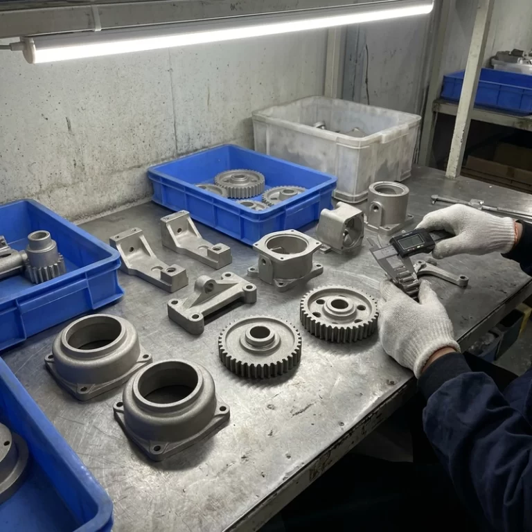
Raw metal printed surfaces are usually rougher than machined surfaces. Bead blasting gives a uniform matte finish and removes loose powder. Tumbling softens edges. Manual polishing can improve touch surfaces or cosmetic faces. Machining may be needed for actual sealing or sliding surfaces. Coatings, anodizing, passivation, or plating depend on alloy and use environment. I would not promise one finish for all surfaces on a complex part.
Support contact faces deserve special attention. A hidden mounting rib can accept heavier scars. A cosmetic surface cannot. A sealing surface should avoid support contact if possible, or it needs machining allowance. The support article on metal 3D printing support design matters here because a bad support decision becomes a finishing problem later.
Inspection Belongs Inside Metal 3D Printing Post-Processing
Inspection is not something I tack on at the end. Dimensional checks after stress relief may tell a different story than checks after machining. CT or X-ray inspection may be needed before or after HIP depending on the quality question. Surface roughness should be measured on the working surface, not only on a convenient flat patch. Hardness, density, tensile coupons, or CMM inspection may be relevant, but only when the part function calls for them.
For terminology and research context, I use neutral resources such as NIST additive manufacturing research. A technical reference does not qualify a part by itself, but it keeps vocabulary and process discussions from drifting. The real quality plan for metal 3D printing post-processing still has to state alloy, process, heat treatment, critical surfaces, tolerances, inspection level, and final finish.
What I Put in the RFQ Notes
For metal 3D printing post-processing, the RFQ notes should not stop at “polish after printing.” I would list the alloy, process route, whether stress relief is required before plate removal, whether HIP is required, which faces need CNC machining, which holes or threads are final, which surfaces are cosmetic, and what inspection evidence is expected. If fatigue matters, say it. If a surface seals fluid, say it. If the part is only a visual metal sample, say that too.
The practical rule is simple enough: print quality, post-process order, machining allowance, and inspection have to be planned together. If they are quoted as separate afterthoughts, the part may still look like a metal part. It just may not behave like the metal component the drawing expected.