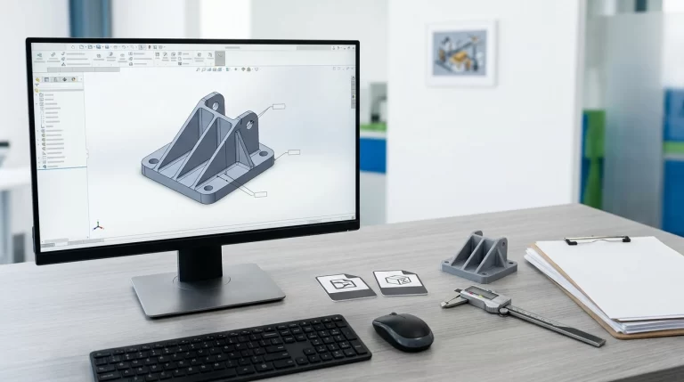
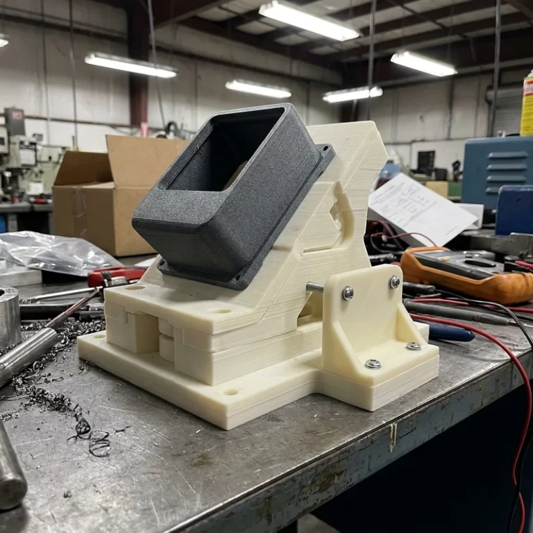
A lab fixture replacement can start with photos when the CAD file is missing. Photos help a supplier understand the shape, damaged area and missing information. They do not, by themselves, establish the dimensions, internal features or performance needed for a replacement that fits and works.
For an engineering fixture, the priority is usually the interfaces: where it mounts, what it contacts and how it carries or locates an object. Prepare those details before asking someone to turn a photograph into an STL. A photo-based decorative model and a functional replacement part solve different problems.
Explain what the fixture does
A non-load-bearing cover may mainly need the right outline and fixing method. A fixture that positions a specimen or connects to equipment may depend on locating faces, hole positions, stiffness and the operating environment.
Tell the reviewer what the part holds, which surfaces contact the equipment or specimen, and which holes or slots provide adjustment or location. Describe where it failed and what was happening at the time. Include known exposure to heat, liquids or cleaning agents. Also distinguish a temporary experimental replacement from a part intended for repeated use.
“Make it the same” leaves these requirements open. A replacement can look similar while having the wrong interface or repeating the cause of the original failure.
Prepare photos for a lab fixture replacement
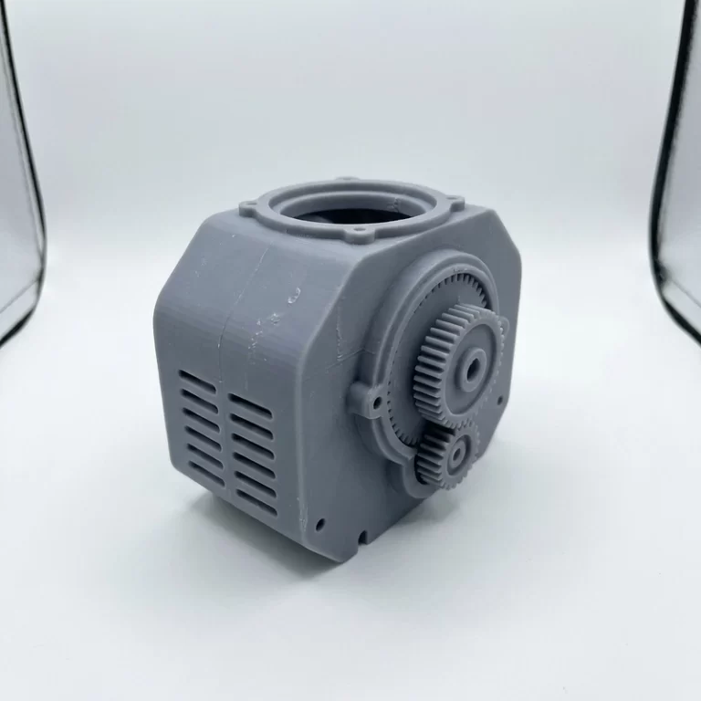
Provide whole-part views from different directions, close-ups of important interfaces, the damaged area, and the part in its mounting environment. If mating components determine fit, show those too.
A scale reference can help explain approximate size, but it does not replace measurement of a critical feature. Perspective, obstruction and camera angle affect what can be inferred from a photograph. An estimated hole spacing should not quietly become an approved assembly dimension.
If the part broke into pieces, photograph the fracture and remaining features as well as the pieces placed together. Existing marks, fastener positions and worn contact areas may help explain how it was used. Avoid including confidential equipment or research details that are unnecessary for the initial review.
Measure the interfaces that control fit
Spend measurement effort on the features that govern assembly and function rather than treating every visible contour as equally important.
| Information | Why it matters | What to provide if uncertain |
|---|---|---|
| Mounting-hole positions and diameters | Controls installation | Measurements and mating fastener information |
| Contact and locating faces | Controls how the fixture works | Marked reference faces and contact regions |
| Outer envelope and movement space | Helps identify interference | Installation views and space restrictions |
| Slots, clips and threads | Controls the connection method | Local measurements, drawings or the original part |
| Original material and environment | Supports material-route review | State unknowns and explain the use conditions |
| Failure location and action | Helps assess whether redesign is needed | Fracture views and a description of the event |
Treat inaccessible internal features as unknown rather than guessing. If an original part is available, ask whether inspection, scanning, additional measurement or disassembly would help. Availability, cost and deliverables for that work need to be agreed separately.
Photos, scans, CAD and print files are different inputs
A photograph is a reference. A scan generally captures surface data. CAD can describe engineering geometry that can be revised. A print mesh supports manufacturing preparation. Converting between them does not automatically recover the original design intent.
Autodesk’s reverse-engineering overview explains the role of captured geometry and measurement. Its guidance on rebuilding CAD from scan data describes using reference geometry to reconstruct a model. These are technical workflows, not evidence that one uploaded photo can produce a precise, validated replacement.
A broken fixture adds another question: which features represent the intended design, and which represent damage? Copying the damaged surface exactly is not necessarily the right repair.
Ask for the file format you will need next
If you expect to change hole positions, revise the structure or consider machining, ask whether STEP and an agreed native CAD file can be included. STEP commonly exchanges solid or surface geometry; it does not necessarily preserve the originating software’s complete parametric history.
STL is a mesh format used in print preparation. It generally does not retain parametric features, and units should be stated separately. Other formats may be appropriate depending on the data and workflow. A file opening successfully does not establish that its dimensions, units or structure are correct.
Agree the deliverables rather than assuming that “modeling included” means everything:
- Model views or a drawing for approval.
- The agreed STEP and, where applicable, native CAD files.
- A print mesh with stated units.
- Critical-interface dimensions and revision identification.
- The physical sample and agreed inspection information.
Clarify rights to use and modify the model, and whether later revisions are included. For supporting file information, see Zesmir’s STL and STEP quotation guide.
Do not choose a replacement material from its color
Review the material and manufacturing route against the interfaces, loads, temperature, cleaning environment and intended use. A similar-looking material may not have the required behavior. A general prototype material should not be assumed suitable for a specialized laboratory application.
Possible routes can include resin printing, nylon printing, other print processes or CNC machining, but photos alone are not enough to select one. If the part relates to pressure, elevated temperature, rotating equipment or another significant hazard, the responsible team should define validation and acceptance requirements before use. A successful fit check is not sufficient evidence of safe performance.
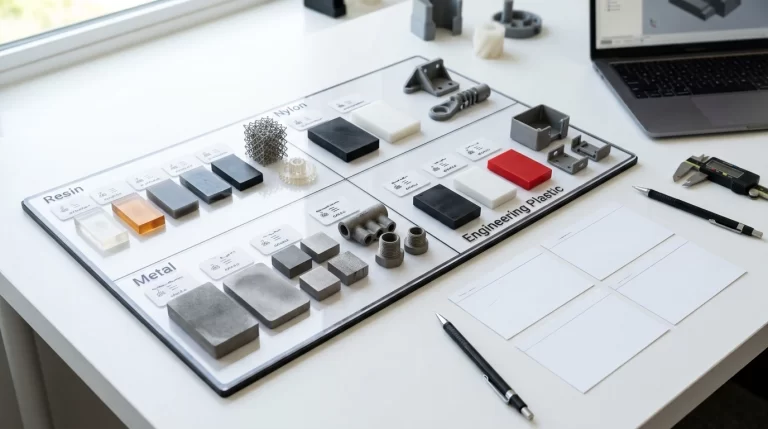
For a replacement-fixture review, Zesmir can consider its SLA 9000HE resin, SLS 3201PA-F nylon, MJF PA12 and FDM ABS routes against the geometry and use conditions. These options do not mean that every fixture is suitable for printing or that the routes are mechanically equivalent. Confirm the proposed grade, mounting interfaces, environment and inspection scope before manufacture.
A review sequence for a lab fixture replacement
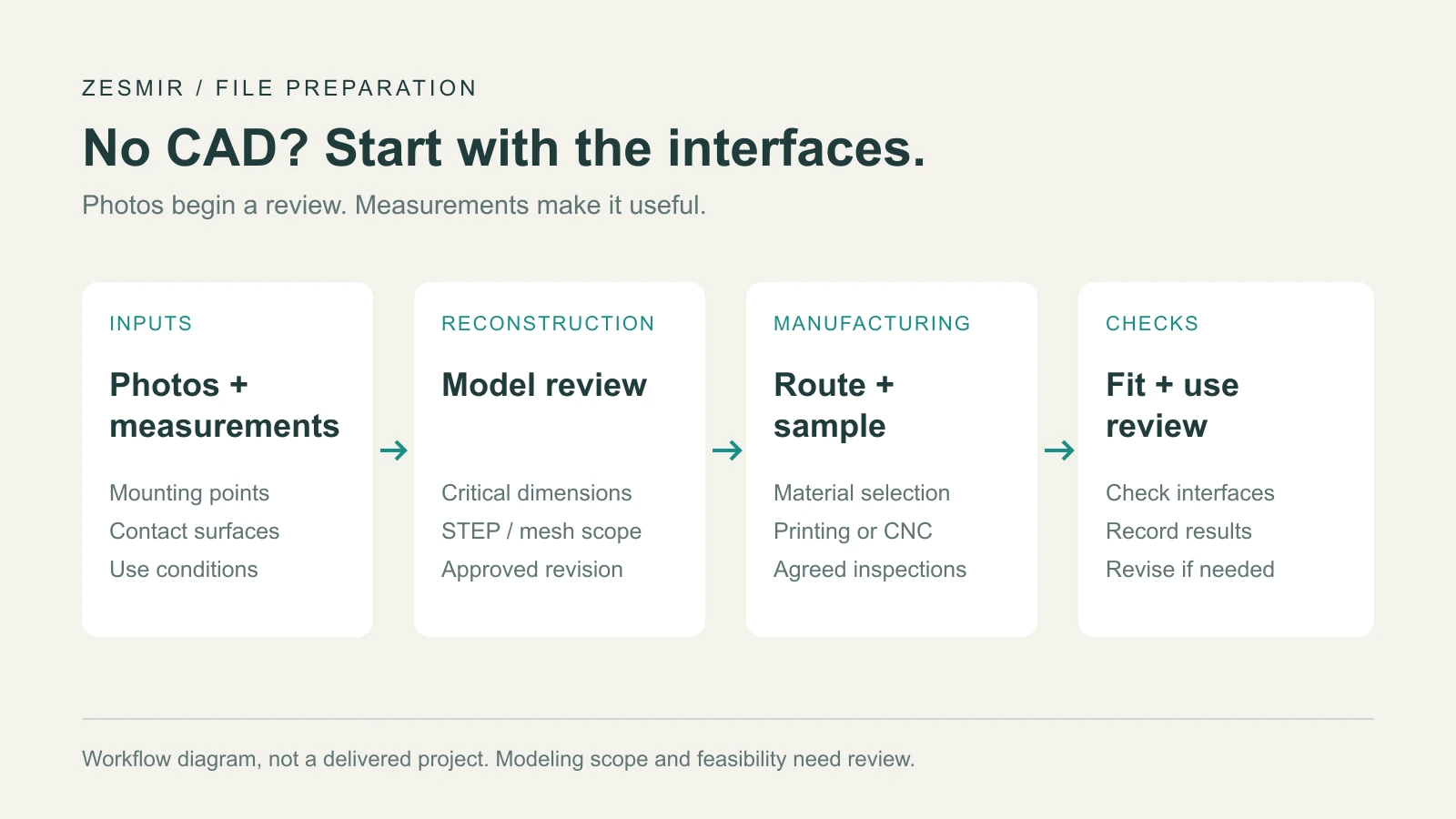
- Send photos, use conditions and known dimensions so missing information can be identified.
- Review the need for measurement, an original part, scanning or new modeling, including scope and cost.
- Confirm critical interfaces, revision, deliverable files and candidate manufacturing routes.
- Approve the model or drawing before making the sample.
- Check assembly and the intended use, then revise before deciding whether to reuse the design.
A small fixture does not always need an elaborate report, but it still needs a basis for approval. Keep modeling, manufacturing, finishing and extra inspection visible in the quote. Free initial quotation review should not be interpreted as free reverse engineering or complete engineering validation.
Questions before sending the RFQ
Can a single photo start the project?
Yes, it can start a conversation. An assembly-dependent fixture will often need critical dimensions, additional views and use information. The reviewer should confirm whether modeling is feasible and whether an original part is needed.
What if the original material is unknown?
State that it is unknown and describe the environment, contact conditions and failure. Do not identify a material from color alone or treat similar appearance as functional equivalence.
Do I still need a drawing if I already made an STL?
A drawing or annotated view is useful where mounting or locating dimensions matter. It identifies the features that must meet requirements rather than relying only on the appearance of the mesh.
Can any laboratory part be copied?
No blanket commitment is appropriate. Rights to reproduce it, functional risks, information quality and manufacturing feasibility need review. Safety-related parts and parts affecting experimental results may require additional validation.
Start with a reviewable information package
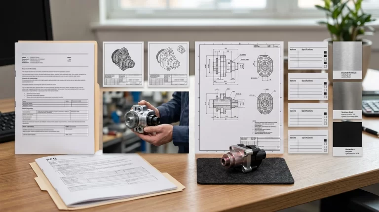
Use Zesmir’s manual RFQ contact page to send fixture photos, installation views, measurements and intended use. Say that no CAD file is available and that the modeling and replacement scope needs review before a manufacturing quote.
The custom 3D printing service page explains the project-review route. Initial review is not a promise to restore a validated engineering part from a photo alone. Modeling availability, material choice, checks and manufacturing should be confirmed for the actual project.