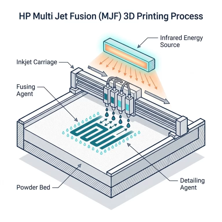
SLS nylon 3D printing guide topics usually start with the same promise: no support structures, strong functional parts, and good design freedom. That is true, but it is incomplete. SLS nylon succeeds because loose powder supports the part during printing, and it fails when the design ignores powder removal, shrinkage, cooling, wall thickness, or surface finish.
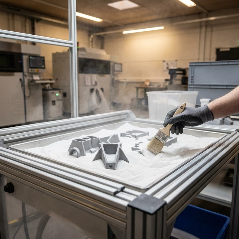
I like explaining SLS as a powder-bed workflow, not a magic box. A thin layer of nylon powder is spread, the laser sinters selected areas, the bed lowers, and the cycle repeats. After the build, the whole cake cools, parts are removed, powder is cleaned out, and the part may be blasted, dyed, tumbled, sealed, or coated. Each step leaves a mark on the final part.
SLS nylon 3D printing guide to powder-bed workflow
The source references layer thickness around 0.05-0.2 mm and laser spot size around 0.1-0.2 mm in common discussions. PA12 powder is usually preheated close to its sintering range so the laser does not have to supply all the energy. That thermal balance is why cooling matters. Pulling parts too early or cooling unevenly can invite warping and dimensional drift.
Because the powder supports the part, SLS can build shapes that would need support in SLA or FDM. Internal channels, nested parts, organic brackets, and functional hinges become easier. The catch is powder removal. A beautiful closed cavity full of trapped powder is not a useful design. Escape holes and access paths belong in the CAD model.
Cooling time is easy to underestimate. A large build may stay warm long after the laser work ends. If parts are dug out too early, they can move while internal stress is still relaxing. For a schedule-sensitive job, I would rather plan cooling time honestly than promise a shipping date based only on laser time.
For accuracy-specific rules, pair this article with Zesmir’s SLS nylon dimensional accuracy. For dyeing and sealing choices, read SLS nylon surface finishing.
Design limits in this SLS nylon 3D printing guide
Wall thickness is the first design check. Thin walls may print but deform during cooling, blasting, or handling. Many PA12 SLS parts start around 1 mm or more for small non-load features, with thicker walls needed for larger functional geometry. Long flat panels should use ribs or curvature. Bosses and holes should be sized for powder texture and shrinkage.
Moving assemblies need clearance. The part may print, but it may not move after powder, blasting, and shrinkage are included. I would not use CAD clearance as the final physical clearance. Small hinges, chain links, and sliding parts should be tested with a coupon first. If a channel must pass air or fluid, design a cleanout route and check actual flow after depowdering.
Part orientation also changes surface and accuracy. A top face, side face, and down-facing face may not have the same texture. If one surface seals against a gasket or locates another component, it should be oriented and inspected deliberately. The cheapest nesting position is not always the best manufacturing position.
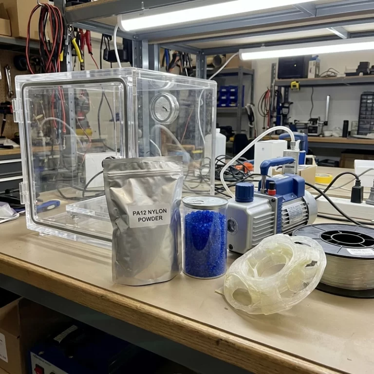
Nylon moisture also matters before and after printing. The source mentions drying PA12 around 80 C for several hours in some workflows, but supplier guidance should decide the real process. For more on this, see nylon 3D printing moisture control.
SLS nylon 3D printing guide to surface and tolerance
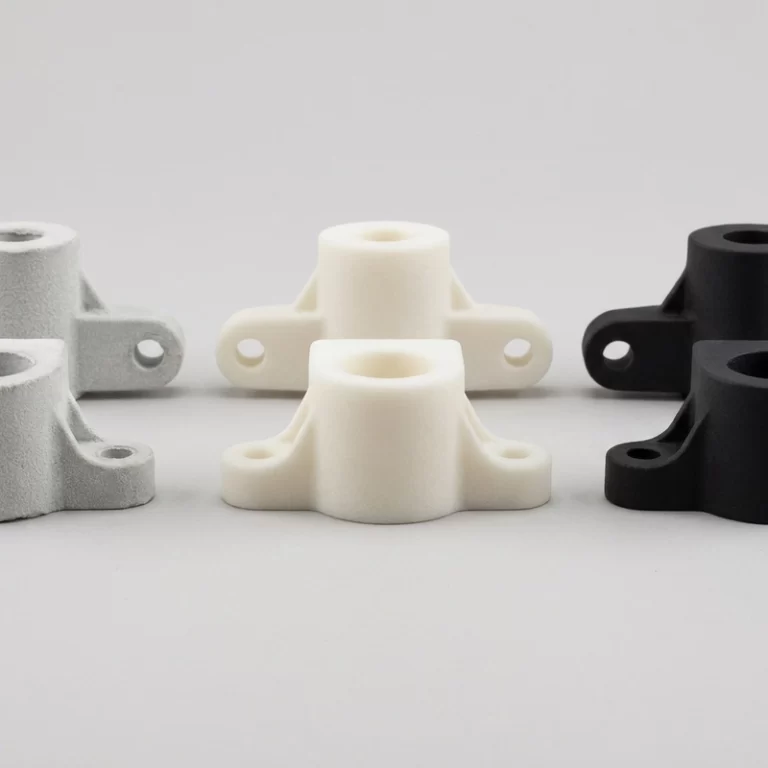
Raw SLS nylon has a powdery, matte texture. It is often acceptable for fixtures and functional prototypes, but consumer-facing parts may need tumbling, dyeing, sealing, coating, or painting. Dyeing black is common because it hides some powder variation. Light colors and brand colors need sample approval. If the part must look molded, SLS may not be the cheapest path after finishing is included.
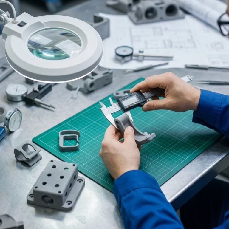
Tolerance should be assigned where it matters. A fixture locating pin, a bearing seat, a screw boss, and a decorative outside wall do not need the same control. For tight datums, consider post-machining. For non-critical surfaces, let normal printed tolerance apply. This keeps both cost and expectation under control.
Powder refresh is another hidden quality item. Reused powder can be economical, but heat history and contamination have to be controlled. When the job is appearance-sensitive or mechanically important, ask whether the process uses a defined refresh ratio and whether the material batch can be repeated.
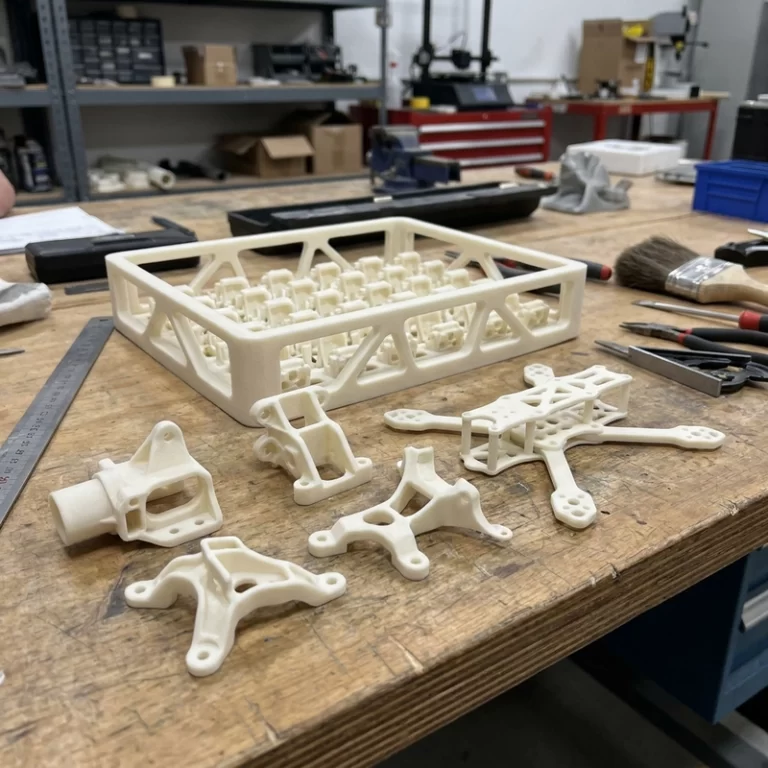
Batch packing also affects the part. SLS makes it tempting to fill every open space in the build chamber, but dense nesting can change heat distribution and cooling behavior. For repeat work, the build layout should not change wildly without checking whether dimensions and surface finish still match the approved sample.
For neutral process language, ISO/ASTM 52900 is a useful reference. It helps separate powder-bed fusion from extrusion, vat photopolymerization, and other additive routes.
When SLS nylon is the right route
- Functional nylon prototypes with complex geometry.
- Small batches where tooling is too slow or expensive.
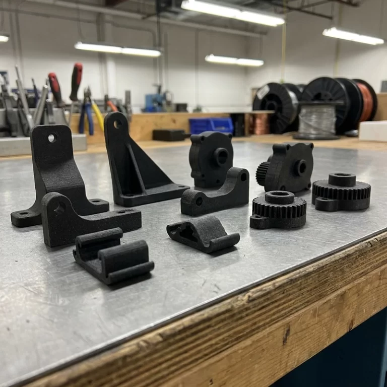
- Fixtures, brackets, housings, drone parts, and medical or education models after proper review.
- Parts that benefit from no support scars and nested build packing.
An RFQ for SLS should include STEP or STL files, target material, quantity, wall thickness concerns, critical dimensions, finish requirement, dye color, and any moving or internal features. This SLS nylon 3D printing guide is not a substitute for design review, but it gives the right questions before the quote is fixed.