SLM parameter optimization is not a search for one perfect laser setting. I look at it as a process window: laser power, scan speed, hatch spacing, layer thickness, powder condition, atmosphere, support strategy, and scan path all pulling on the same melt pool. Change one number without checking the others and the part can move from dense fusion to lack of fusion, keyhole pores, spatter, or distortion very quickly.

The trap in SLM parameter optimization is treating energy density like a verdict. It is useful shorthand. It helps organize test coupons. But two parameter sets can show the same calculated energy density and still produce different melt-pool shapes because peak power, exposure time, powder absorption, scan order, gas flow, and local heat history are not the same. I use energy density to plan tests, not to approve parts.
SLM Parameter Optimization Starts With the Melt Pool
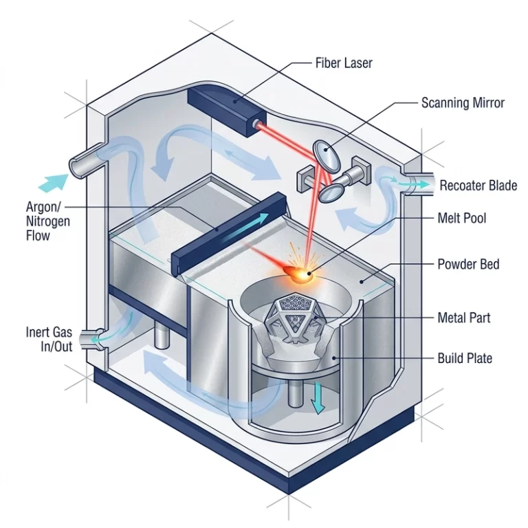
Laser power decides how much energy enters the powder. Scan speed decides how long the beam stays over a point. Hatch spacing decides how much neighboring melt tracks overlap. Layer thickness decides how much powder has to be melted and how much remelting reaches the previous layer. Those four settings do not behave independently, even though a slicer or machine interface may list them as separate boxes.
If power is too low, or speed is too fast, the melt pool may not penetrate deeply enough. That is where irregular lack-of-fusion pores show up, often along track boundaries or layer interfaces. If power is too high, or speed is too slow, the metal can vaporize more aggressively. That can bring spatter, rough edges, and keyhole-type pores. Tight hatch spacing can improve overlap, but it also adds heat. Thick layers can improve build speed, but only if there is enough energy to melt through the layer and bond into the previous one.
| Parameter | When it is too low or too weak | When it is too high or too aggressive | What I check |
|---|---|---|---|
| Laser power | Shallow melt pool, weak bonding, lack of fusion | Keyhole pores, spatter, rough edges | Density coupon, cross-section, surface roughness |
| Scan speed | Overheating if the beam dwells too long | Incomplete melting and unmelted powder | Melt-track continuity and pore shape |
| Hatch spacing | Too tight can add heat and slow the build | Too wide can leave poor track overlap | Layer interface inspection and density |
| Layer thickness | Thin layers raise build time | Thick layers need stronger remelting | Density, surface finish, and dimensional drift |
SLM Parameter Optimization Should Follow the Defect Shape
I do not like adjusting SLM settings from the surface alone. A shiny surface can still hide lack of fusion. A rough surface does not tell me whether the defect is gas, keyhole, contamination, or poor overlap. The defect shape matters. Round gas pores often point toward gas entrapment, powder moisture, oxidation, or melt-pool instability. Irregular voids with sharp edges usually push me toward insufficient energy input, poor overlap, or layer bonding trouble. Cracks bring a different set of questions: alloy sensitivity, residual stress, contamination, thermal gradient, and support strategy.
That is why I pair this topic with SLM metal 3D printing defects. If the cross-section shows lack-of-fusion voids at scan-track boundaries, raising power, slowing scan speed, tightening hatch spacing, or reducing layer thickness may be reasonable test directions. If the part shows round pores with heavy spatter, simply adding power may make the problem worse. Powder condition, oxygen control, focus calibration, and shielding gas flow may need to be checked first.
Powder and Atmosphere Can Ruin Good Numbers
A clean parameter sheet does not rescue bad powder. Powder size distribution, reuse count, oxidation, moisture, flowability, and contamination all change how the laser couples energy into the bed. Reused powder can still work, but it needs control. If the oxygen level, powder batch, or sieve condition changes, the old parameter window may not behave the same way. This is where metal 3D printing powder quality becomes part of SLM parameter optimization, not a separate purchasing detail.
Atmosphere matters too. Excess oxygen can change chemistry and surface behavior. Poor gas flow can leave spatter in the scan area. Powder that looks acceptable in the feed container can still behave badly if it carries moisture or if fine particles have built up after reuse. I want the parameter record to include powder batch, reuse count, drying or storage condition, oxygen level, and gas flow notes. Without that record, a good coupon can become hard to repeat later.
Scan Strategy Is Not Decoration
Scan vectors control how heat moves through the layer. In SLM parameter optimization, this is not decorative path planning; it changes stress and local heat buildup. Rotating scan direction between layers, often by 60 to 90 degrees, can reduce repeated weak planes and spread residual stress. Island scanning can break a large layer into smaller thermal regions. Contour scanning can improve edges, but edge energy has to be controlled. Too little contour energy gives weak borders; too much can raise edges or roughen the sidewall.
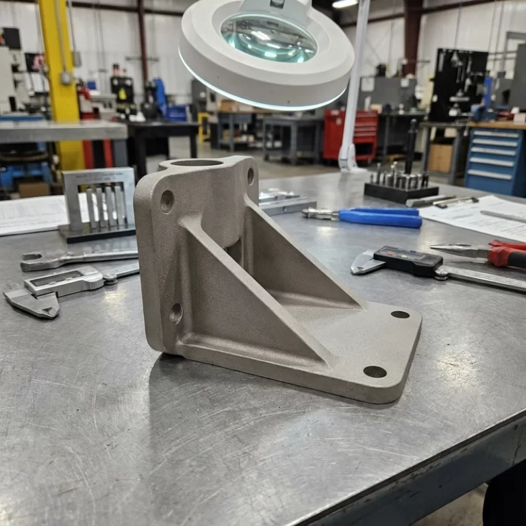
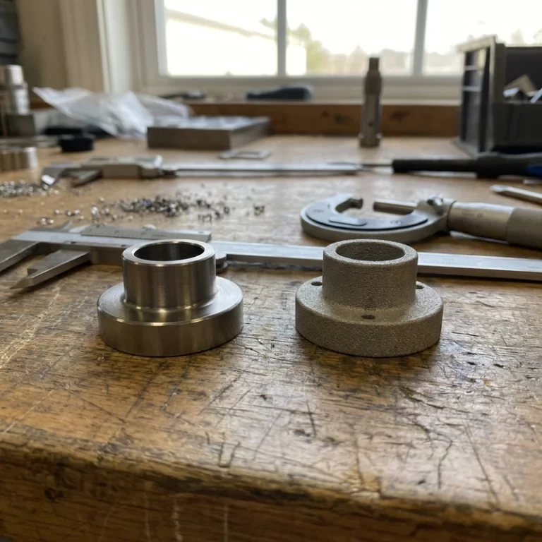
Thin walls, holes, deep grooves, and overhangs may need local strategy instead of one global setting. Critical holes and shafts still need machining allowance in many metal prints because printed circular features can shrink, ovalize, or roughen depending on orientation and thermal stress. That is where metal 3D printing post-processing enters the same conversation. Parameter work and machining allowance should not be planned by two people who never talk to each other.
Build a Window, Not a Lucky Coupon
The safer way to approach SLM parameter optimization is to print small coupons first, not a complicated customer part. Hold layer thickness and orientation steady, then vary power, speed, and hatch spacing in a controlled matrix. Measure density. Cut and polish cross-sections. Look at pore shape. Record surface roughness. If the part is functional, add tensile, hardness, or fatigue testing where the requirement calls for it. A coupon that only looks good is not enough evidence.
After the basic window looks stable, I test geometry risks: thin walls, overhangs, small holes, support removal zones, and heat-heavy sections. This is where a parameter set that worked on a cube may fail on a real bracket. The coupon tells you the process can work. The geometry coupon tells you whether it can work on the shape you actually need.
Inspection Closes SLM Parameter Optimization
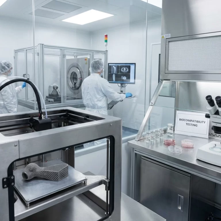
SLM parameter optimization should end with evidence, not confidence. Visual inspection catches spatter, roughness, and distortion. Metallographic sections show pore shape and bonding. CT or X-ray can help map internal defects in critical parts. CMM or 3D scanning shows whether thermal distortion is under control. Tensile, hardness, and fatigue tests may be needed when the part carries load. The right inspection stack depends on the risk of the part.
For neutral background on additive manufacturing terminology and research, I use references such as NIST additive manufacturing research. A reference link does not qualify a parameter set by itself. The real record still needs the alloy, powder batch, reuse count, oxygen level, laser power, scan speed, hatch spacing, layer thickness, scan strategy, support settings, preheat if used, cooling route, heat treatment, and inspection result.
My RFQ note for metal parts is blunt: send the alloy, STEP file, drawing tolerances, critical surfaces, quantity, heat treatment needs, inspection level, and any post-machining requirement. If the part is fatigue-loaded or pressure-related, say it early. SLM parameter optimization is not just making a print finish; it is making a repeatable manufacturing route that leaves enough evidence to trust the part.