
Sheet metal prototyping usually fails in boring places: a hole too close to a bend, a flange the press brake cannot grip, a powder-coated slot that suddenly becomes tight, or an enclosure lid that fits in CAD but rocks on the bench. I do not treat it as a flat laser-cut job once the part has bends, inserts, finish, and assembly surfaces.
The first review is simple. I check whether the part can be cut, bent, finished, and assembled in the same condition the buyer expects to approve. If any one of those steps is unclear, the prototype can look clean and still be wrong.
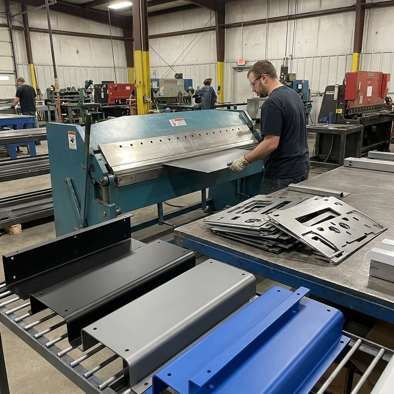
Sheet metal prototyping starts before the flat pattern
A flat DXF is enough for a simple panel. A folded enclosure needs more: bend direction, inside radius, material thickness, finish, hardware, and the surfaces that must line up after forming. Bend allowance and bend deduction are not decorative CAD settings. They decide flange length, hole shift, corner relief, and whether the formed part lands near the intended size.
Hole position near a bend is one of the first traps I look for. A round hole can become oval after bending if it sits too close to the bend line. A connector cutout may be correct on the flat pattern and shifted after springback. If the hole is for a display, PCB standoff, fan, hinge, or cable gland, I mark it as a critical feature before the quote stage.
Bend order and tooling access are real constraints
Some sheet metal shapes are easy to draw and awkward to form. Deep boxes, return flanges, narrow channels, and closed shapes can block the tooling after the first few bends. A one-piece design may look cheaper, but splitting the enclosure into two laser-cut and riveted parts can be cleaner than forcing a press brake into a bad sequence.
I also check flange length. Very short flanges can be hard to grip and bend accurately. Sharp inside corners may crack or create inconsistent forming, especially when the material is stiff or the radius is too aggressive. A reasonable bend radius, corner relief, and a clear bend drawing save more time than arguing after the first sample is folded the wrong way.
| Design check | What can go wrong | What I ask for |
|---|---|---|
| Hole near bend | Distortion or hole shift | Distance from bend line and critical-hole note |
| Short flange | Poor tooling grip | Minimum flange review before release |
| Closed enclosure | Bend sequence blocked | Split, weld, rivet, or redesign option |
| Powder coating | Slots and tabs become tight | Coating allowance on mating features |
| Inserted hardware | Wrong thread direction or pullout | Hardware list and insertion side |
Material, finish, and hardware change the final fit
Aluminum, stainless steel, mild steel, and galvanized steel do not bend the same way. Aluminum is light and useful for enclosures, but springback and coating choice still matter. Stainless steel is stronger and corrosion resistant, but forming force and tool marks need attention. Mild steel is cost-friendly and often powder coated, which means finish thickness must be part of the fit plan.
Powder coating is where many clean prototypes get annoying. A tab-and-slot fit that works in raw metal can become tight after coating. A hinge line can scrape. PEM nuts, studs, rivet nuts, and threaded inserts also need position, thread size, and insertion direction. If the prototype will hold electronics, I ask about grounding points, masked areas, vents, EMI contact surfaces, and heat paths early, not after painting.
Sheet metal prototyping RFQ checks I would not skip
A useful RFQ includes STEP, flat DXF if available, bend drawing, material, thickness, finish, hardware list, and marked critical dimensions. For formed parts, I care more about the final assembly dimensions than the flat pattern alone. If the project is moving from prototype to a small batch, I also ask whether the same finish, hardware, and packaging will be used for approval and production.
Sheet metal work often sits beside other prototype routes. A printed bracket may be faster for a shape check, but a bent aluminum housing is more honest for a thin metal enclosure. For hybrid projects, the notes on CNC machining after 3D printing and 3D printing file preparation are useful because the same rule applies: mark the surfaces that actually control fit. For terminology across manufacturing routes, ISO/ASTM 52900 is a clean outside reference.
My rule for sheet metal prototyping is plain: approve the formed, finished, assembled part, not the flat drawing in isolation. If the part has bends, inserts, coating, and mating hardware, all four need to be reviewed before the sample becomes the batch reference.
On a first article, I normally put the finished part on the table with the real screws, inserts, gasket, PCB, display window, or bracket it will meet. That sounds slow, but it catches the problems CAD screenshots miss: a lid that flexes when tightened, a coated tab that scratches into a slot, a rivet nut that blocks a cable path, or a vent pattern that leaves too little flat area for a label. These are ordinary sheet metal prototyping problems, not exotic failures.
I also separate cosmetic approval from dimensional approval. A brushed or powder-coated surface can look acceptable while a connector opening is off by enough to ruin assembly. If the part will ship overseas, I check exposed corners, coated edges, and packaging contact points as well. Thin metal parts can arrive bent or scratched if the packing plan is treated as an afterthought.