
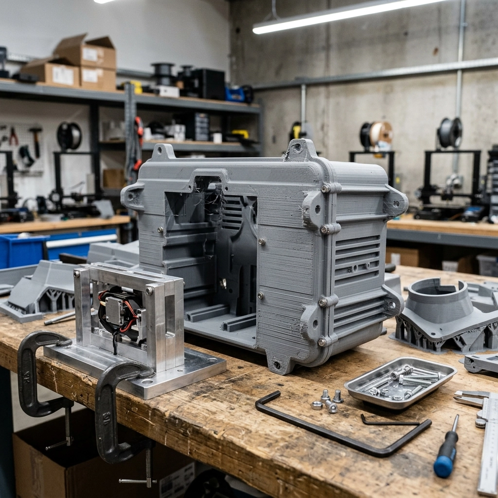

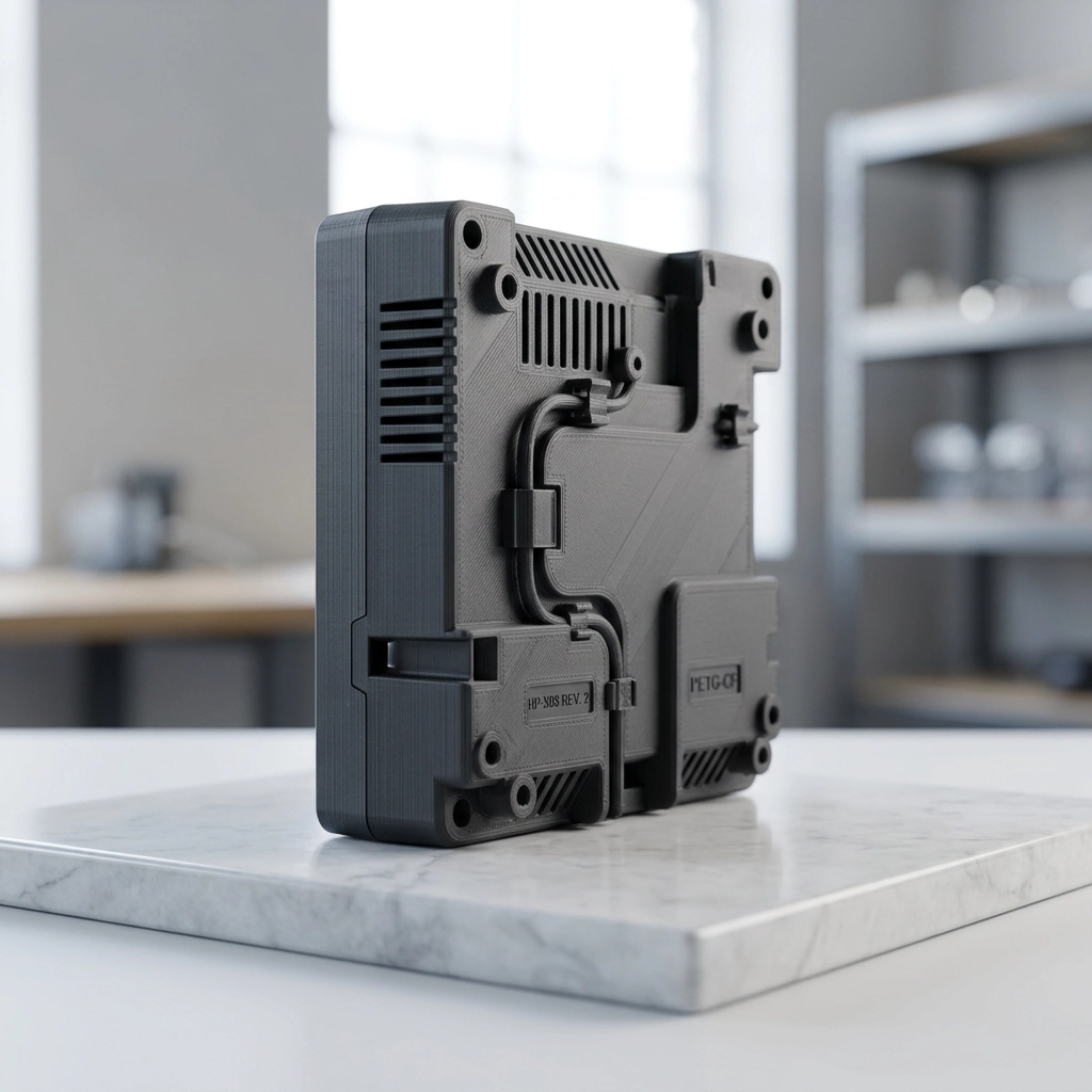
FDM Large Prototype 3D Printing Service
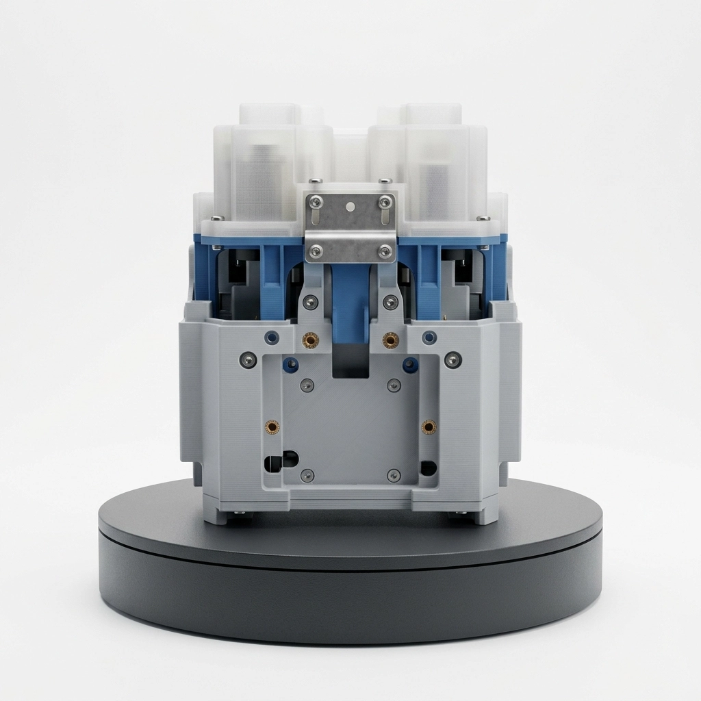
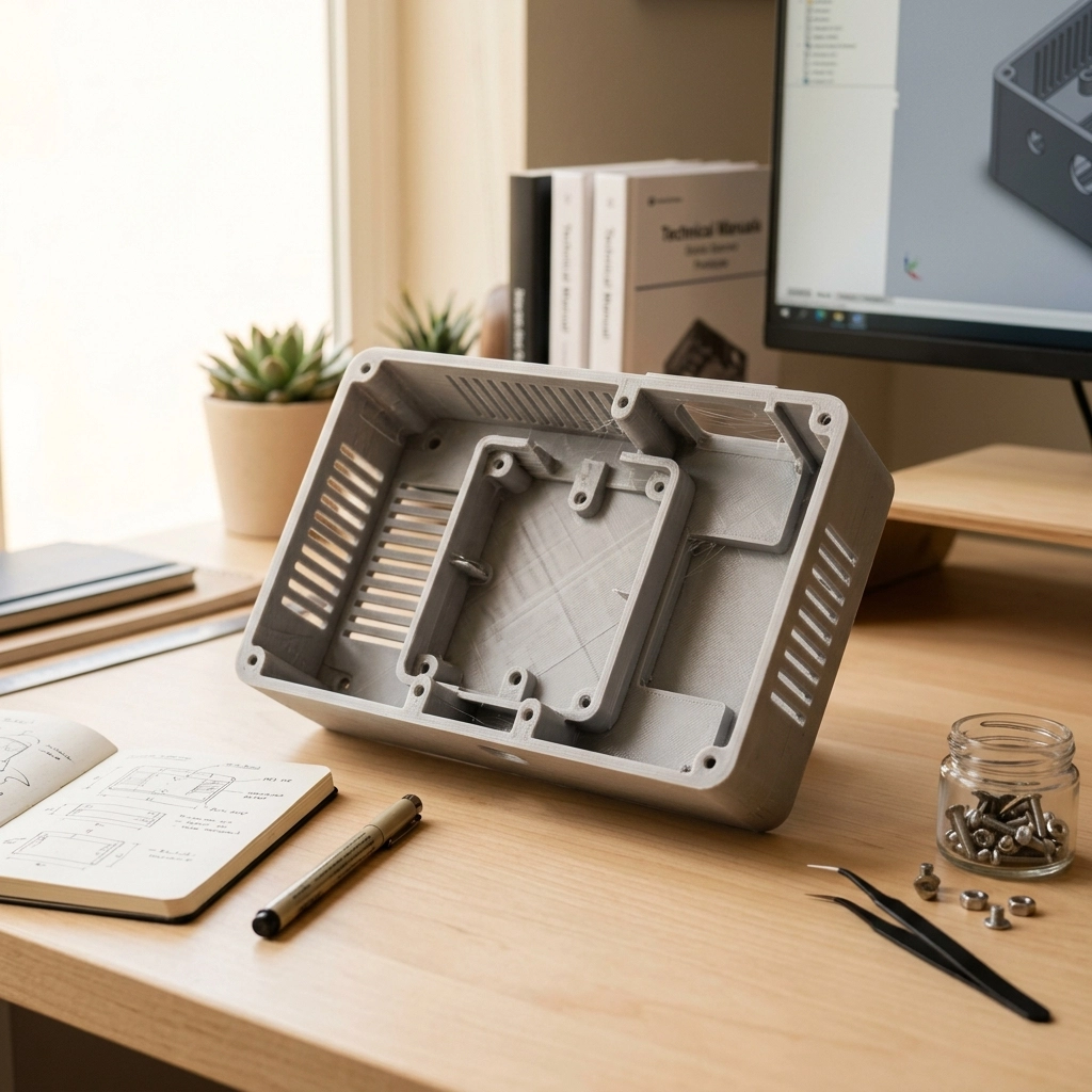
Large-format FDM printing for housings, fixtures, ducts and full-scale development models. Send STEP or STL files for review of material, segmentation, warping, layer direction, joints and finishing.
Description
FDM large prototype 3D printing service is useful for housings, fixtures, mockups, ducts and full-scale development parts that would consume too much resin or powder-bed capacity. Size is the attraction. It is also where the familiar FDM problems become harder to ignore: shrinkage accumulates over distance, flat sections lift, seams drift and a long print can fail late.
A large part should not be quoted by bounding-box dimensions alone. I want to know whether it must carry load, align with purchased hardware, survive outdoor use or simply show the design at full scale. Those answers decide material, build direction, segmentation and finishing.
FDM Large Prototype 3D Printing Service Begins With a One-Piece Decision
A model fitting inside the machine does not mean it should be printed in one piece. One-piece construction avoids assembly seams, but it may create a long build, heavy supports, poor orientation for important faces and a larger loss when something fails near the end.
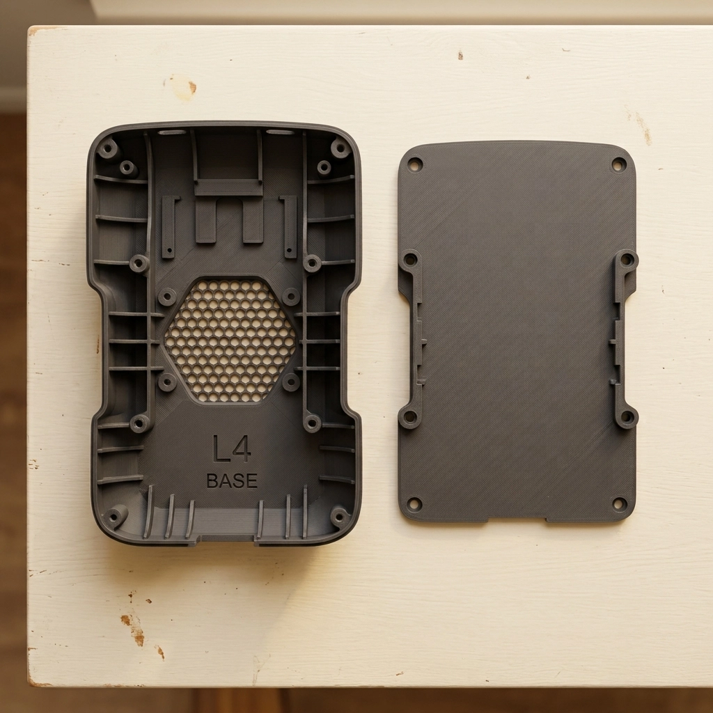
Splitting the model can improve orientation, reduce support and make finishing easier. The split line then becomes a designed interface. It needs locating geometry, adhesive area or mechanical fastening, plus access for clamps and cleanup. A random planar cut made only to fit the build volume usually leaves a visible seam and weak alignment.
I normally place a joint where the geometry already changes direction, where it can be reached from both sides or where a trim line will hide it. Cosmetic priority and assembly accuracy matter more than dividing every section into equal lengths.
Large FDM Parts Are Thermal Structures During the Build
Material is deposited hot onto material that has already begun to cool. The temperature difference and polymer shrinkage create stress. On a small part, the movement may be modest. Across a long base, shallow tray or tall wall, the same behavior can show up as lifted corners, bowed panels, cracked layers or a joint that no longer meets its matching section.
Heated build conditions, material control, suitable orientation and stable wall design all help, but there is no universal anti-warp setting. ORNL research on large-scale thermoplastic extrusion notes that repeated deposition of hot material onto cooler material produces residual stress and that the issue becomes more significant as scale increases. Geometry and process conditions have to be considered together.
Broad flat panels are especially unforgiving. Gentle curvature, ribs, returns and shorter unsupported spans can make the shell more stable. A thick solid edge attached to a thin panel may create another problem by cooling differently. More material is not automatically a better fix.
Layer Direction Must Follow the Load Path
FDM parts are built from deposited roads and layers. Strength and fracture behavior depend on orientation, material, bead bonding and geometry. A bracket that pulls across the layers is a different part from the same bracket loaded mainly within them. Infill percentage cannot rescue a poor load path by itself.
Show load direction, fastener locations and any area that will be repeatedly flexed. Perimeters, local solid regions, ribs and fillets can then be placed where they contribute. For fixtures and jigs, the clamping force may matter more than the weight of the part being held. For a visual mockup, surface direction and finish may take priority instead.
Material Selection Starts With the Environment
PLA, PETG, ABS, ASA, PC and nylon are not price tiers of the same plastic. They differ in stiffness, impact response, heat behavior, moisture sensitivity, UV performance, printability and finishing. Filled grades add another set of tradeoffs, including different surface texture and tool wear.
For an FDM large prototype 3D printing service RFQ, state whether the part sits indoors, rides in a vehicle, stays near a heat source, sees sunlight, contacts chemicals or carries a sustained load. If a regulated requirement applies, the exact material documentation and full production route must be reviewed. A generic polymer family name is not certification.
The engineering plastic material selection guide compares common polymer families without pretending one grade is best for every prototype.
Walls, Ribs and Infill Do Different Jobs
Wall count controls the outer shell and often contributes more to local durability than filling the entire interior. Ribs support broad faces and transfer load. Infill supports top surfaces and changes stiffness, weight and print time. These settings interact, but they are not interchangeable.
A large decorative cover may need stable walls and sparse internal structure. A fixture around a bolt may need local solid material, a washer seat and a load-spreading rib. Screw bosses should connect into the surrounding shell rather than stand as isolated towers. If an insert or nut is planned, include installation access and enough material around it.
Design the Seam Before Choosing the Adhesive
A butt joint offers little alignment and puts the bond line under direct stress. Depending on the model, a tongue-and-groove, lap, scarf, keyed socket, dowel or bolted flange can provide better location and more bonding area. The joint should still allow for printed variation and adhesive thickness.
Dry-fit the sections before filling or painting. If the joint is forced into alignment with clamps, the assembled shell may spring back after release. Reference holes, internal brackets or a temporary assembly jig can keep several large panels in the same coordinate system.
The adhesive must be compatible with the actual polymer and service environment. Surface preparation, gap size and cure conditions matter. I would not hide a poorly designed joint under filler and call the structural problem solved.
Surface Finish Can Become the Largest Labor Item
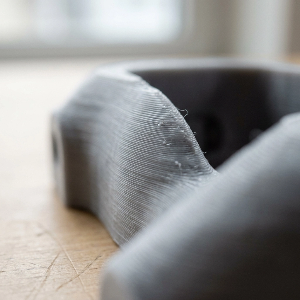
Raw FDM shows layer lines, start points, support contact and seam transitions. For an FDM large prototype 3D printing service order, sanding, filler, primer and paint can produce a presentation surface, but every stage adds labor and can soften edges or alter fit. A large part has a great deal of surface area. Asking for a smooth painted shell may cost more in finishing than in printing.
Mark A-surfaces, hidden faces and no-sand features. If a hole, insert pocket or mating edge must remain accurate, protect it from filler and coating. Sometimes the practical route is to print the bulk shape, machine selected references through the CNC and 3D printing hybrid service, then finish only the visible areas.
FDM Large Prototype 3D Printing Service RFQ Notes
- STEP or STL file with final dimensions and confirmed units;
- end use, load direction and environmental conditions;
- one-piece preference or acceptable split locations;
- mating components, fasteners, inserts and critical interfaces;
- raw, assembled, sanded, primed or painted finish;
- quantity, first-article check and dimensional inspection needs.
ASTM’s F3529 guide covers design considerations for polymer material extrusion. It provides a process framework, while the selected machine, material and geometry still set the practical limits.
Use the 3D printing design guidelines to prepare wall, fit and file notes, or return to the custom 3D printing service hub if FDM may not be the best route. For a manual FDM large prototype 3D printing service review, send the model, size, quantity and finish through the RFQ contact page.