
SLM Metal 3D Printing Service
SLM metal 3D printing for complex brackets, manifolds, internal channels and near-net metal parts. Send STEP files and drawings for review of supports, residual stress, heat treatment, CNC allowance and inspection.
Description
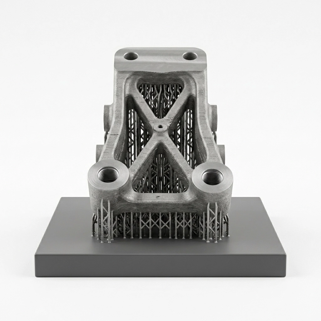
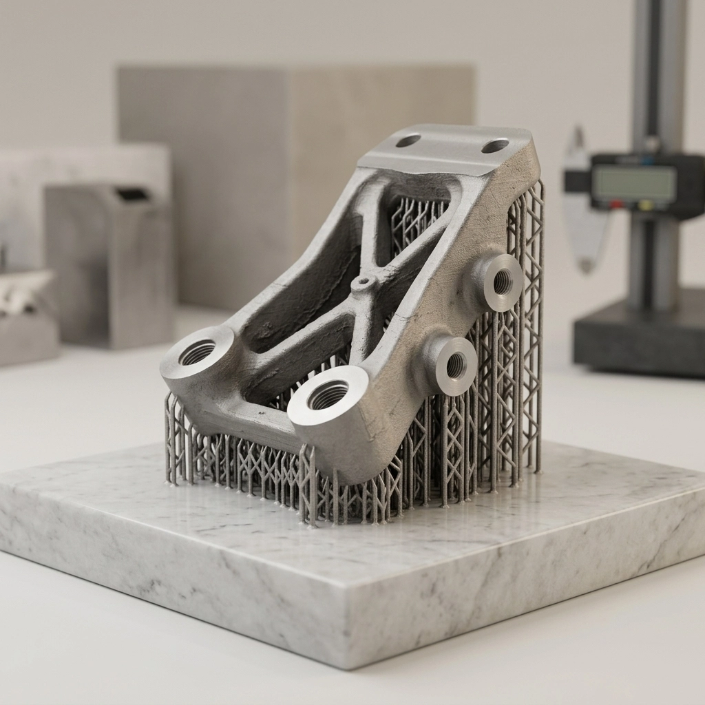
SLM metal 3D printing service makes the most sense when geometry earns its place in the process: internal channels, compact manifolds, lattice sections, lightweight brackets or features that would require several machined pieces to be joined. The printed shape is normally a near-net component, not a finished precision part.
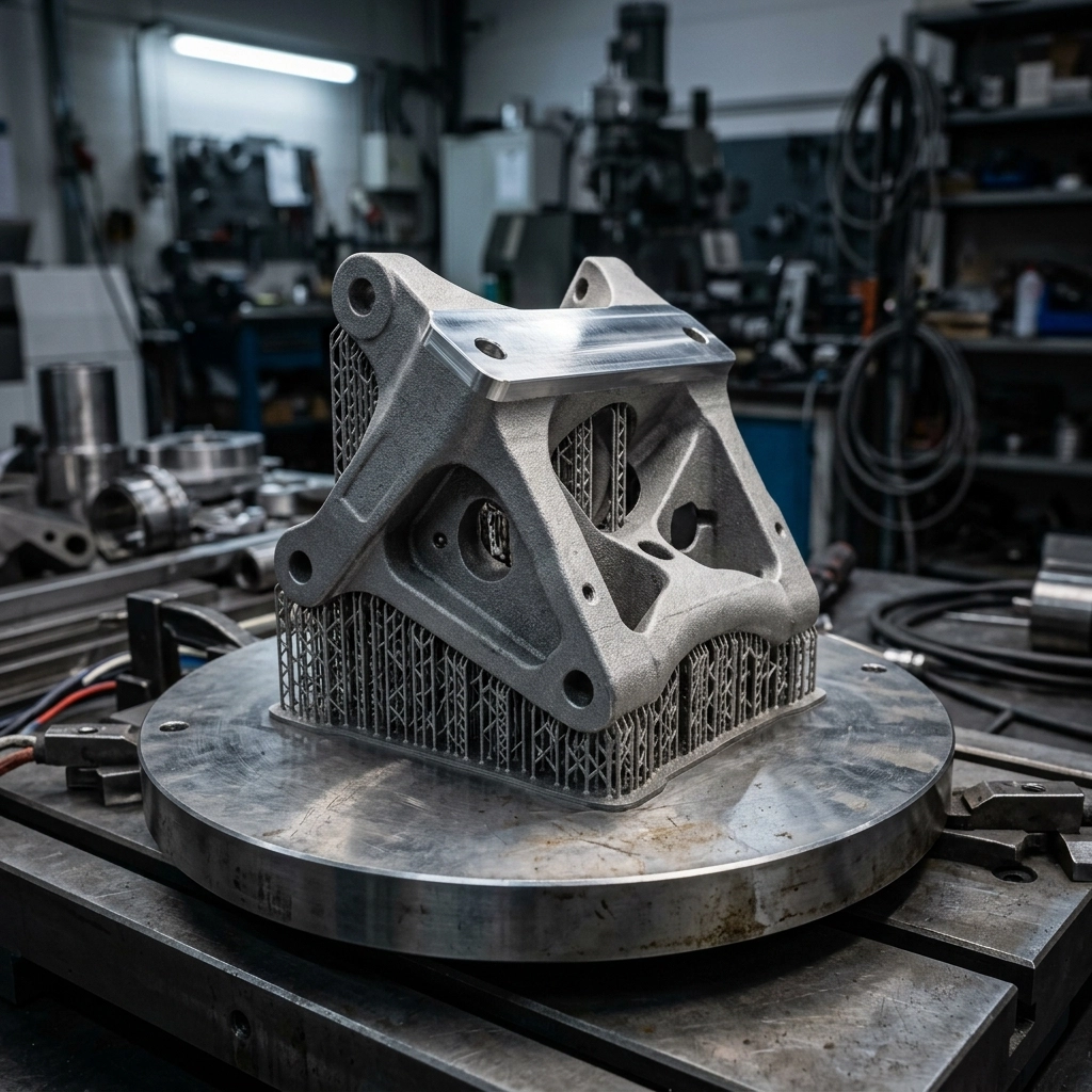
The build plate, supports, stress relief, powder removal, support cutting and CNC work all belong in the manufacturing plan. Leaving those steps until after the model is nested can turn an impressive build into a part with no usable datum, no tool access or no practical way to clear an internal passage.
An SLM Metal 3D Printing Service Starts at the Build Plate
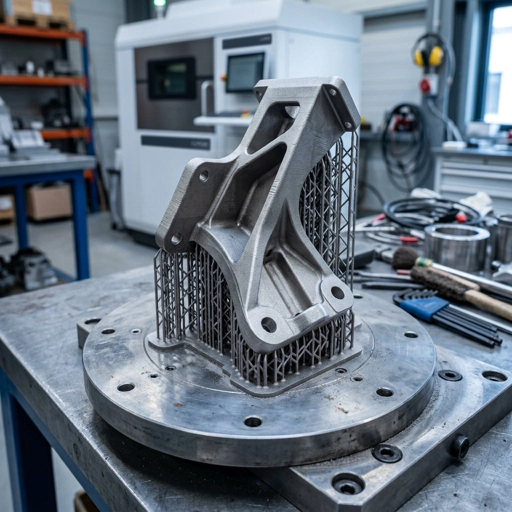
SLM is a widely used commercial term for laser-based metal powder bed fusion. A laser melts selected regions of a thin powder layer, the platform indexes and the cycle repeats. The local melting and rapid cooling create steep temperature gradients. Supports do more than hold an overhang; they can anchor the part, conduct heat toward the plate and resist movement during the build.
This is why orientation cannot be chosen only to reduce height. Rotating a bracket may shorten the build but move supports onto a sealing face. Standing a manifold differently may help an external wall yet make internal powder removal worse. The orientation has to balance support access, heat flow, distortion, surface priority and later machining.
I normally mark the critical faces and planned datums before discussing the support layout. A CAD model without that information leaves the manufacturing team to decide which surfaces may be sacrificed.
Residual Stress Changes the Order of Operations
Metal powder bed fusion creates material and geometry in the same thermal cycle. Residual stress can pull a part while it is attached to the plate or release distortion when the component is cut free. NIST research on laser powder bed fusion describes how temperature gradients generate residual stress and can push parts outside tolerance. That is a process-control issue, not a cosmetic defect.
The correct sequence depends on alloy, geometry and qualified procedure. Stress relief may be planned while the part remains attached to the plate; plate removal, support removal and further heat treatment then follow in a controlled order. I would not write one heat-treatment recipe into a general RFQ. The exact cycle belongs to the alloy condition, material specification and supplier’s validated process.
Read the SLM metal printing overview for a closer look at what happens after the build cools. The metal 3D printing post-processing guide covers the downstream operations that are easy to miss during quoting.
Support Removal and Powder Escape Need Physical Access
An internal channel may be printable and still be impractical. Loose metal powder must be removed, and the route may need vibration, air flow, vacuum or other controlled handling appropriate to the material and facility. A blind pocket, lattice core or serpentine channel needs defined openings and a way to verify that cleaning is complete. Safety procedures for metal powder are part of production control and should not be improvised at the workbench.
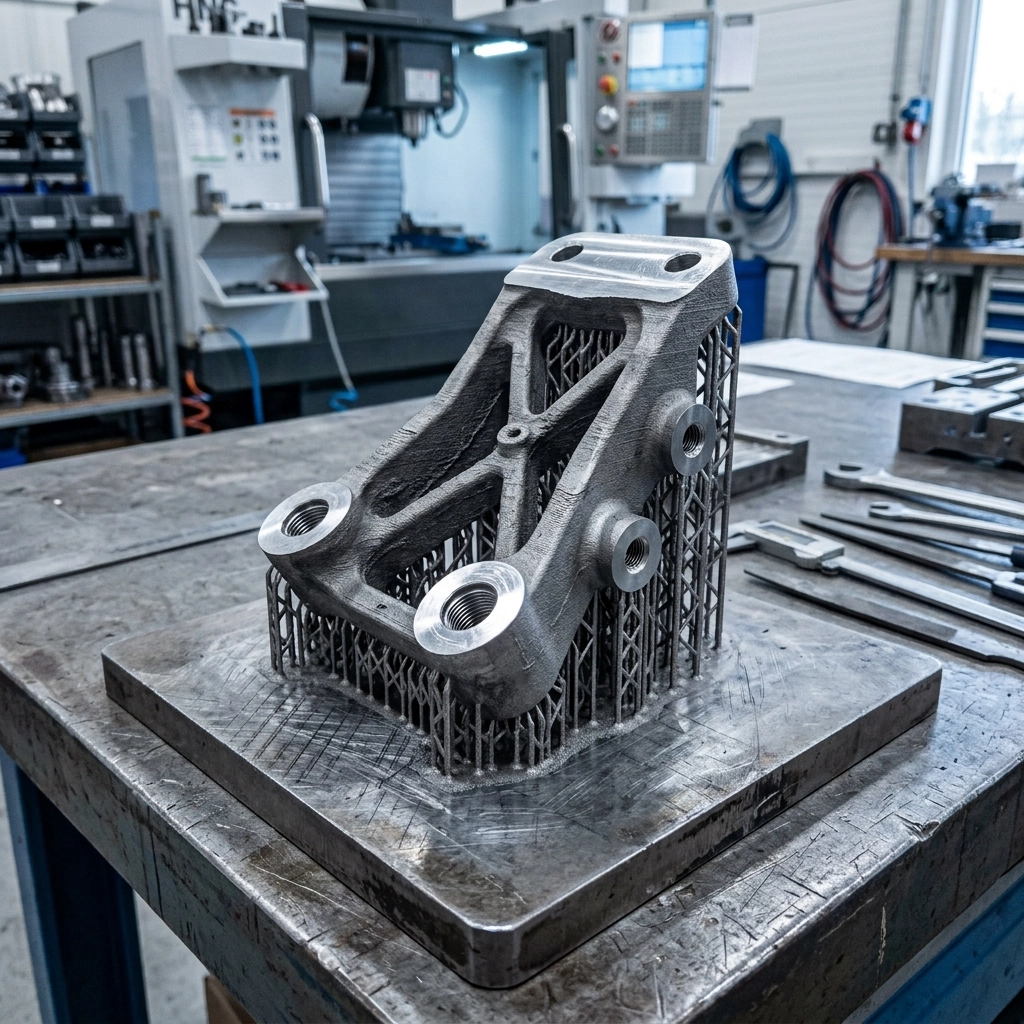
External supports need tool access too. A support trapped behind a flange may be difficult to cut or grind without damaging the part. If the supported surface later becomes a mating face, leave enough stock for cleanup or machining. Support marks are expected process features; where they appear should be decided before the build.
Material Names Must Include Alloy and Final Condition
“Stainless steel,” “aluminum” or “titanium” is not a purchasing specification. The alloy designation, powder route, required heat-treatment condition and acceptance requirements matter. Mechanical properties can depend on build orientation, process parameters, heat treatment and specimen preparation. A generic online property table should not be used as a certificate for a production part.
For an SLM metal 3D printing service RFQ, state whether the part is a visual prototype, a fit sample, a functional test component or a production-intent item. Critical or regulated applications may require process qualification, material traceability, witness coupons, nondestructive examination and a documented inspection plan. Those requirements need to be priced before manufacturing, not added after shipment.
Plan CNC Allowance and Datums in the Printed Model
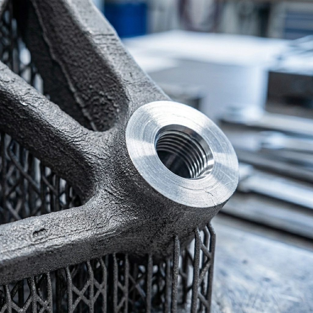
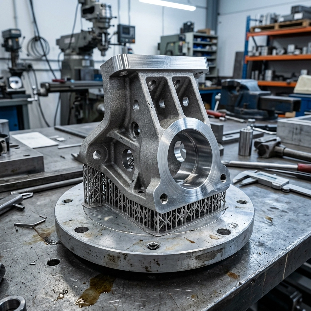
Printed holes, sealing faces and bearing seats should not automatically be treated as finish-machined features. When a dimension controls function, the model may need machining stock plus a fixture strategy that can locate the irregular printed body.
- Identify the primary, secondary and tertiary datums.
- Mark bores, threads, sealing lands and mounting faces that need CNC finishing.
- Leave accessible stock without blocking powder removal or creating an unbuildable mass.
- Confirm that tools and inspection probes can reach the feature.
- Decide whether sacrificial locating features are needed for fixturing.
The CNC and 3D printing hybrid service is the more accurate route when complex shape and precision interfaces belong in the same part.
Inspection Must Match the Failure Risk
A caliper check is useful for accessible envelope dimensions but says little about internal porosity, a buried channel or the condition of a machined sealing surface. Inspection may involve CMM measurement, surface roughness checks, density evaluation, CT scanning, metallography or mechanical testing, depending on the requirement. Not every prototype needs all of them. The buyer should identify what can fail and what evidence is needed to accept the part.
ASTM lists ISO/ASTM 52904 for production control of metal powder bed fusion used in critical applications. Citing a standard is not the same as claiming compliance; the applicable edition, scope and required records must be agreed in the order.
When an SLM Metal 3D Printing Service Is the Wrong Route
A simple block, plate, turned shaft or easily milled bracket often belongs on conventional CNC equipment. SLM adds powder handling, build preparation, thermal risk and post-processing. It earns that complexity when it consolidates assemblies, creates inaccessible channels, reduces mass or makes geometry that machining cannot reach economically.
Binder jetting may suit a different mix of quantity, geometry, density and finishing requirements. Our SLM versus binder jetting comparison explains why the two routes should not be priced as substitutes without reviewing the part.
SLM Metal 3D Printing Service RFQ Data
- STEP file plus a drawing that marks datums and critical tolerances;
- alloy designation, required condition and any material standard;
- internal channels, powder-removal openings and cleanliness criteria;
- heat treatment, support removal, CNC, polishing or coating scope;
- sample and batch quantity, first-article approval and delivery target;
- inspection method, documentation and acceptance criteria.
Return to the custom 3D printing service hub when process selection is still open. For a manual SLM metal 3D printing service review, upload the STEP file, drawing and quantity through the RFQ contact page. The first discussion should define the finished part, not just the printed shape.